171 KiB
第36天 增强的内部网关路由协议
Enhanced Interior Gateway Routing Protocol, EIGRP
Gitbook:ccna60d.xfoss.com
你可以在 https://github.com/gnu4cn/ccna60d 上 fork 本项目,并提交你的修正。
本书结合了学习技巧,包括阅读、复习、背书、测试以及 hands-on 实验。
本书译者用其业余时间完成本书的翻译工作,并将其公布到网上,以方便你对网络技术的学习掌握,为使译者更有动力改进翻译及完成剩下章节,你可以 捐赠译者。
第36天任务
- 阅读今天的课文
- 复习昨天的课文
- 完成今天的实验
- 阅读ICND2记诵指南
增强的内部网关路由协议是一种由思科开发的、专有内部网关协议(a proprietary Interior Gateway Protocol(IGP) that was developed by Cisco)。EIGRP包含了一些传统的距离矢量特性,比如水平拆分(split horizon),还包含了与那些被链路状态路由协议所用到的类似特性,比如增量更新(EIGRP includes traditional Distance Vector characteristics, such as split horizon, as well as characteristics that are similar to those used by Link State routing protocols, such as incremental updates)。
尽管有着链路状态路由协议的某些特性,但EIGRP是被分类到距离矢量路由协议类别中的,被指为一种高级的距离矢量路由协议(an advanced Distance Vector routing protocol)。EIGRP直接在IP上运行,使用协议编号88。
今天将学习以下内容:
- 思科公司EIGRP概述与基础知识, Cisco EIGRP overview and fundamentals
- EIGRP配置基础, EIGRP configuration fundamentals
- EIGRP的各种报文, EIGRP messages
- EIGRP的邻居发现与邻居维护, EIGRP neighbour discovery and maintenance
- 各种度量值、弥散更新算法(DUAL)与拓扑表,Metrics, DUAL, and the topology table
- 相等与不相等开销下的负载均衡,equal cost and unequal cost load sharing
- 采用EIGRP作为默认路由,default routing using EIGRP
- EIGRP网络中的水平分割, split horizon in EIGRP networks
- EIGRP的存根路由,EIGRP stub routing
- EIGRP的路由汇总,EIGRP route summarisation
- 掌握被动接口,understanding passive interfaces
- 掌握EIGRP路由器ID的用法,understanding the use of the EIGRP router ID
- EIGRP的日志与报表,EIGRP logging and reporting
本课程对应了以下CCNA大纲要求:
- 配置并验证EIGRP(单一自治系统),configure and verify EIGRP(single AS)
- 可行距离/可行的后续路由/报告的距离/通告的距离分别是什么,Feasible Distance/Feasible Successor routes/Reported Distance/Advertised Distance
- 可行性条件,Feasiblity condition
- 度量值综合,Metric composition
- 路由器ID,Router ID
- 自动汇总,Auto summary
- 路径选择,path selection
- EIGRP的负载均衡,load balancing
- 开销一样时
- 开销不同时
- 什么是EIGRP的被动接口,passive interfaces
思科EIGRP概述与基础知识
为解决其先前的专有距离矢量路由协议 -- 内部网关路由协议(Interior Gateway Routing Protocol, IGRP)的某些缺陷,思科公司开发了EIGRP。相比路由信息协议(Routing Information Protocol, RIP),IGRP确实有着一些改进,比如对更多跳数的支持;但仍然有着那些传统距离矢量路由协议的局限,这些局限如下所示:
- 发送完整的周期性路由更新,sending full periodic routing updates
- 跳数限制,a hop limitation
- 缺少对变长子网掩码的支持,the lack of VLSM support
- 收敛速度慢,slow convergence
- 缺少防止环回形成的机制,the lack of loop prevention mechanisms
与传统距离矢量路由协议往邻居发送包含所有路由信息的周期性路由更新不同,EIGRP发送的是非周期性的、增量式路由更新,以将路由信息在整个路由域中分发(unlike the traditional Distance Vector routing protocols, which send their neighbours periodic routing updates that contain all routing information, EIGRP sends non-periodic incremental routing updates to ditribute routing information throughout the routing domain)。只有在网络拓扑发生变化时,才会发送EIGRP增量更新。
默认下的RIP(一种以前的CCNA考试项目)有着15的跳数限制,这就令到RIP只适合于小型网络。EIGRP默认跳数限制为100; 但此数值可被管理员在配置EIGRP时,使用路由器配置命令metric maximum-hops <1-255>, 予以手动调整。这就令到EIGRP具备对有着多达数百台路由器网络的支持能力,使其具备了更大的可伸缩性,从而对较大型网络也是适合的。
增强的IGRP采用了两个独特的类型/长度/数值三联体数据结构来表示和传输路由条目(Enhanced IGRP uses two unique Type/Length/Value(TLV) triplets to carry route entries)。这两个TLVs分别是内部EIGRP路由TLV与外部EIGRP路由TLV(the Internal EIGRP Route TLV and the External EIGRP Route TLV), 分别用于内部及外部的EIGRP路由。两种TLVs都包含了一个8位的前缀长度字段(an 8-bit Prefix Length field), 用于指明用于目的网络子网掩码的位数。包含在此字段中的该信息,就令到EIGRP能够支持不同的子网划分了。
增强的IGRP比起传统的距离矢量路由协议收敛得快得多。除了仅仅依赖于计时器,EIGRP还使用其拓扑表中的信息,来找出那些替代路径。EIGRP也可以在未能于本地路由器的拓扑表中找出替代路径的情况下,向邻居路由器查询信息。本课程模块后面会讲到EIGRP的拓扑表。
而为了确保整个网络中没有环回路径,EIGRP使用了弥散更新算法(Diffusing Update Algorithm, DUAL),使用此算法来对邻居通告的所有路由进行追踪,并随后选出到目的网络最优的无环回路径。弥散更新算法是EIGRP的一个核心概念,将在本课程模块的稍后讲到。
EIGRP配置基础
EIGRP Configuration Fundamentals
在思科IOS软件中,是通过使用全局配置命令router eigrp [ASN],来开启增强的IGRP的。关键字[ASN]指定EIGRP的自治系统编号(autonomous system number, ASN),这是一个32位整数,大小介于1-65535之间。除了本章后面将涉及的其它因素之外,运行EIGRP的那些路由器都必须位处同一自治系统中,以成功形成邻居关系。在全局配置命令router eigrp [ASN]之后, 路由器就转变为EIGRP路由器配置模式(EIGRP Router Configuration mode)了,在这里就可以对那些与EIGRP有关的参数进行配置了。所配置的ASN,可在命令show ip protocols的输出中进行验证,如下面所示:
R1#show ip protocols
Routing Protocol is “eigrp 150”
    Outgoing update filter list for all interfaces is not set
    Incoming update filter list for all interfaces is not set
    Default networks flagged in outgoing updates
    Default networks accepted from incoming updates
    EIGRP metric weight K1=1, K2=0, K3=1, K4=0, K5=0
    EIGRP maximum hopcount 100
    EIGRP maximum metric variance 1
...


[Truncated Output]
而除了show ip protocols命令,命令show ip eigrp neighbours会打印出所有EIGRP邻居,以及这些邻居各自自治系统的信息。该命令及其可用选项,将在本课程模块的后面进行详细讲解。在那些运行了多个EIGRP实例的路由器上,可使用show ip eigrp [ASN]命令,来查看只与在此命令中所指定的自治系统有关的信息。下面的输出演示了这个命令的使用:
R1#show ip eigrp 150 ?
  interfaces  IP-EIGRP interfaces
  neighbors   IP-EIGRP neighbors
  topology    IP-EIGRP topology table
  traffic     IP-EIGRP traffic statistics
在上面的输出中,150就是自治系统编号(ASN)。如show ip eigrp命令没有指定自治系统,那么在思科IOS软件中该命令默认将打印出所有EIGRP实例的信息。
而一旦处于路由器配置模式(Router Configuration mode),就要使用network命令,来指明要在哪些网络(接口上)开启EIGRP路由了(once in Router Configuration mode, the network command is used to specify the network(s) (interfaces) for which EIGRP routing will be enabled)。在使用network命令并指明了一个大的有类网络后,该启用了EIGRP的路由器将完成以下动作:
- 对位处该指明的有类网络范围里的网络,开启EIGRP,EIGRP is enabled for networks that fall within the specified classful network range.
- 以这些直连子网,生成EIGRP的拓扑表,the topology table is populated with these directly connected subnets.
- 从这些与子网关联的接口,发出EIGRP Hello 数据包,EIGRP Hello packets are sent out of the interfaces associated with these subnets.
- EIGRP将这些网络,经由更新报文,通告给EIGRP邻居,EIGRP advertises the network(s) to EIGRP neighbours in Update messages.
- 在报文交换的基础上,那些EIGRP路由,此时就被加入到路由器的IP路由表中,Based on the exchange of messages, EIGRP routes are then added to the IP routing table.
比如假设某台路由器上配置了以下这些环回接口:
Loopback0-- IP地址10.0.0.0/24Loopback1-- IP地址10.0.0.1/24Loopback2-- IP地址10.0.0.2/24Loopback3-- IP地址10.0.0.3/24
如EIGRP已开启使用,且将路由器配置命令network与大的有类10.0.0.0/8网络一道进行了使用,同时所有4个环回接口(all four Loopback interfaces)又都开启了EIGRP路由的话,那么下面就给出了此种情况下show ip eigrp interfaces的输出演示:
R1#show ip eigrp interfaces
IP-EIGRP interfaces for process 150
                     Xmit Queue   Mean    Pacing Time    Multicast      Pending
Interface      Peers Un/Reliable  SRTT    Un/Reliable    Flow Timer     Routes
Lo0            0         0/0         0        0/10            0             0
Lo1            0         0/0         0        0/10            0             0
Lo2            0         0/0         0        0/10            0             0
Lo3            0         0/0         0        0/10            0             0
可使用show ip protocols命令,来对大的有类10.0.0.0/8网络上EIGRP的启用情况,进行验证。此命令的输出如下所示:
R1#show ip protocols
Routing Protocol is “eigrp 150”
    Outgoing update filter list for all interfaces is not set
    Incoming update filter list for all interfaces is not set
    Default networks flagged in outgoing updates
    Default networks accepted from incoming updates
    EIGRP metric weight K1=1, K2=0, K3=1, K4=0, K5=0
    EIGRP maximum hopcount 100
    EIGRP maximum metric variance 1
    Redistributing: eigrp 150
    EIGRP NSF-aware route hold timer is 240s
    Automatic network summarization is in effect
    Maximum path: 4
    Routing for Networks:
        10.0.0.0
    Routing Information Sources:
        Gateway         Distance    Last Update
    Distance: internal 90 external 170
使用命令show ip eigrp topology,可查看到EIGRP的拓扑表。此命令的输出如下所示:
R1#show ip eigrp topology
IP-EIGRP Topology Table for AS(150)/ID(10.3.3.1)
Codes: P - Passive, A - Active, U - Update, Q - Query, R - Reply,
       r - reply Status, s - sia Status
P 10.3.3.0/24, 1 successors, FD is 128256
        via Connected, Loopback3
P 10.2.2.0/24, 1 successors, FD is 128256
        via Connected, Loopback2
P 10.1.1.0/24, 1 successors, FD is 128256
        via Connected, Loopback1
P 10.0.0.0/24, 1 successors, FD is 128256
        via Connected, Loopback0
注意: 本课程模块稍后会对拓扑表、EIGRP的Hello数据包及更新数据包进行详细讲解。本小节仅着重于EIGRP的配置实施(EIGRP configuration implementation)。
使用network命令来指明一个大的有类网络(a major classful network),就令到位于该有类网络中的多个子网,得以在最小配置下同时被通告出去。但可能存在管理员不想对某个有类网络中的所有子网,都开启EIGRP路由的情形。比如,参考前一示例中R1上所配置的环回接口,假设只打算对10.1.1.0/24及10.3.3.0/24子网开启EIGRP路由,而不愿在10.0.0.0/24及10.2.2.0/24开启EIGRP路由。那么很明显这在使用network命令时,对这些网络(也就是10.1.1.0及10.3.3.0)予以指明就可以做到,思科IOS软件仍会将这些语句,转换成大的有类10.0.0.0/8网络,如下所示:
R1(config)#router eigrp 150
R1(config-router)#network 10.1.1.0
R1(config-router)#network 10.3.3.0
R1(config-router)#exit
尽管有着上面的配置,但show ip protocols命令给出的确实下面的输出:
R1#show ip protocols
Routing Protocol is “eigrp 150”
    Outgoing update filter list for all interfaces is not set
    Incoming update filter list for all interfaces is not set
    Default networks flagged in outgoing updates
    Default networks accepted from incoming updates
    EIGRP metric weight K1=1, K2=0, K3=1, K4=0, K5=0
    EIGRP maximum hopcount 100
    EIGRP maximum metric variance 1
    Redistributing: eigrp 150
    EIGRP NSF-aware route hold timer is 240s
    Automatic network summarization is in effect
    Maximum path: 4
    Routing for Networks:
        10.0.0.0
    Routing Information Sources:
        Gateway     Distance        Last Update
Distance: internal 90 external 170
注意: 一个常见的误解就是,关闭EIGRP的自动汇总特性,就能解决此问题;但是,这与
auto-summary命令一点关系都没有。比如,假设对在前一示例中的配置执行了no auto-summary命令,如下所示:
R1(config)#router eigrp 150
R1(config-router)#network 10.1.1.0
R1(config-router)#network 10.3.3.0
R1(config-router)#no auto-summary
R1(config-router)#exit
show ip protocols命令仍将显示对网络10.0.0.0/8开启了EIGRP,如下面的输出所示:
R1#show ip protocols
Routing Protocol is “eigrp 150”
    Outgoing update filter list for all interfaces is not set
    Incoming update filter list for all interfaces is not set
    Default networks flagged in outgoing updates
    Default networks accepted from incoming updates
    EIGRP metric weight K1=1, K2=0, K3=1, K4=0, K5=0
    EIGRP maximum hopcount 100
    EIGRP maximum metric variance 1
    Redistributing: eigrp 150
    EIGRP NSF-aware route hold timer is 240s
    Automatic network summarization is not in effect
    Maximum path: 4
    Routing for Networks:
        10.0.0.0
    Routing Information Sources:
        Gateway     Distance        Last Update
Distance: internal 90 external 170
为了提供到对那些开启EIGRP路由的网络进行更细粒度的控制,思科IOS软件支持在对EIGRP进行配置时,将通配符掩码与network语句一起配合使用(in order to provide more granular control of the networks that are enabled for EIGRP routing, Cisco IOS software supports the use of wildcard masks in conjunction with the network statement when configuring EIGRP)。这里的通配符掩码,以与ACLs中用到的通配符掩码类似的方式运作,而与网络的子网掩码是不相干的。
作为一个示例,命令network 10.1.1.0 0.0.0.255将匹配到网络10.1.1.0/24、10.1.1.0/26及10.1.1.0/30网络。参考上一输出中所配置的那些环回借口(the Loopback interfaces),为将R1配置为对10.1.1.0/24及10.3.3.0/24子网开启EIGRP路由,且不对10.0.0.0/24子网或10.2.2.0子网开启,就应将其如下面那样进行配置:
R1(config)#router eigrp 150
R1(config-router)#network 10.1.1.0 0.0.0.255
R1(config-router)#network 10.3.3.0 0.0.0.255
R1(config-router)#exit
使用命令show ip protocols,就可对此配置进行验证,如下所示:
R1#show ip protocols
Routing Protocol is “eigrp 150”
    Outgoing update filter list for all interfaces is not set
    Incoming update filter list for all interfaces is not set
    Default networks flagged in outgoing updates
    Default networks accepted from incoming updates
    EIGRP metric weight K1=1, K2=0, K3=1, K4=0, K5=0
    EIGRP maximum hopcount 100
    EIGRP maximum metric variance 1
    Redistributing: eigrp 150
    EIGRP NSF-aware route hold timer is 240s
    Automatic network summarization is in effect
    Maximum path: 4
    Routing for Networks:
        10.1.1.0/24
        10.3.3.0/24
    Routing Information Sources:
        Gateway     Distance        Last Update
Distance: internal 90 external 170
此外,还可以使用命令show ip eigrp interfaces,确认到仅已对Loopback1与Loopback3开启了EIGRP路由:
R1#show ip eigrp interfaces
IP-EIGRP interfaces for process 150
                     Xmit Queue   Mean    Pacing Time    Multicast      Pending
Interface      Peers Un/Reliable  SRTT    Un/Reliable    Flow Timer     Routes
Lo1            0         0/0         0        0/10            0             0
Lo3            0         0/0         0        0/10            0             0
如上面所示,因为这里的通配符掩码配置,而仅在Loopback1和Loopback3上启用了EIGRP路由。
这里重要的是记住除了使用通配符掩码,也可以使用子网掩码来配置network命令。在此情况下,思科IOS软件将翻转子网掩码,而使用通配符掩码来保存该命令。比如,参照路由器上同样的环回借口,路由器R1也可被如下这样进行配置:
R1(config-router)#router eigrp 150
R1(config-router)#network 10.1.1.0 255.255.255.0
R1(config-router)#network 10.3.3.0 255.255.255.0
R1(config-router)#exit
基于此种配置,就在运行配置中输入了下面的参数(这里使用了管道(pipe),取得运行配置中感兴趣的部分):
R1#show running-config | begin router eigrp
router eigrp 150
network 10.1.1.0 0.0.0.255
network 10.3.3.0 0.0.0.255
auto-summary
通过上面的配置可以看出,可与那些show命令一道运用管道,来获得更细的粒度。这对于那些有着编程知识的人来说,是一种熟悉的概念。
如将某个网络上的特定地址与通配符一起使用,那么思科IOS软件将执行一次逻辑与运算(a logical AND operation), 从而确定出那个要启用EIGRP的网络。比如,在执行了network 10.1.1.15 0.0.0.255命令时,思科IOS软件会执行以下动作:
- 将通配符掩码翻转为子网掩码值
255.255.255.0 - 执行一次逻辑与操作
- 将命令
network 10.1.1.0 0.0.0.255加入到配置中
本示例中所用到的network配置,如下面输出所示:
R1(config)#router eigrp 150
R1(config-router)#network 10.1.1.15 0.0.0.255
R1(config-router)#exit
那么基于此配置,路由器上的运行配置,就会显示如下内容:
R1#show running-config | begin router eigrp
router eigrp 150
network 10.1.1.0 0.0.0.255
auto-summary
如上面的配置所示,不管是使用通配符子网掩码,还是子网掩码,都会在思科IOS软件中造成同样的操作,并得到同样的network语句配置。
真实世界的部署
当在生产网络中对EIGRP进行配置时,一般做法都是使用全0的通配符掩码或全1的子网掩码。比如,
network 10.1.1.1 0.0.0.0及network 10.1.1.1 255.255.255.255,两个命令都会执行同样的动作。全0的通配符掩码或全1的子网掩码的使用,就将思科IOS软件配置为与一个具体接口地址进行匹配,而不考虑在接口本身上所配置哦子网掩码了。这两个命令都会匹配到配置了比如10.1.1.1/8、10.1.1.1/16、10.1.1.1/24, 以及10.1.1.1/30等地址的接口。这些命令的用法如下面的输出所示:
R1(config)#router eigrp 150
R1(config-router)#network 10.0.0.1 0.0.0.0
R1(config-router)#network 10.1.1.1 255.255.255.255
R1(config-router)#exit
show ip protocols命令将验证到路由器对于两个network语句,都是以相似的方式进行处理的,如下所示:
R1#show ip protocols
Routing Protocol is “eigrp 150”
    Outgoing update filter list for all interfaces is not set
    Incoming update filter list for all interfaces is not set
    Default networks flagged in outgoing updates
    Default networks accepted from incoming updates
    EIGRP metric weight K1=1, K2=0, K3=1, K4=0, K5=0
    EIGRP maximum hopcount 100
    EIGRP maximum metric variance 1
    Redistributing: eigrp 150
    EIGRP NSF-aware route hold timer is 240s
    Automatic network summarization is in effect
    Maximum path: 4
    Routing for Networks:
        10.0.0.1/32
        10.1.1.1/32
    Routing Information Sources:
        Gateway     Distance        Last Update
Distance: internal 90 external 170
在使用了全1的子网掩码或全1的通配符掩码时,就会在所指定的(匹配的)接口上开启EIGRP,同时将通告那个接口所位处的网络。也就是说,EIGRP不会通告上面输出中的/32地址,而是通告基于配置在匹配接口上的子网掩码的具体网络。此配置的用法,是独立于配置所匹配具体接口子网掩码的(when a subnet mask with all ones or a wildcard mask with all zeros is used, EIGRP is enabled for the specified(matched) interface and the network the interface resides on is advertised. In other words, EIGRP will not advertise the /32 address in the above but, instead, the actual network based on the subnet mask configured on the matched interface. The use of this configuration is independent of the subnet mask configuration on the actual interface matched)。
EIGRP的各种报文
EIGRP Messages
本小节将对EIGRP所用到的各种类型的报文进行说明。但是,在深入到各种不同报文类型前,首要的是对EIGRP数据包头部有扎实的掌握,这正是包含这些报文的地方。
EIGRP数据包头部
EIGRP Packet Header
尽管对EIGRP数据包格式的具体了解,是超出CCNA考试要求的,但对EIGRP数据包头部的扎实掌握,对于完整理解EIGRP这种路由协议的整体运作原理,是很重要的。下图36.1对EIGRP数据包头部进行了演示:
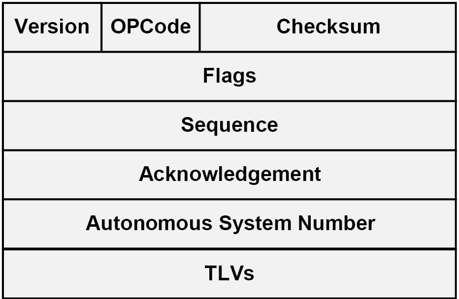 图 36.1 -- EIGRP数据包头部的各种字段
在EIGRP数据包头部,其中的4位版本字段(the 4-bit Version field)用于表明该协议的版本。当前的思科IOS镜像都支持EIGRP版本1.x。后面的4为OPcode字段(the 4-bit OPCode field),则指定了EIGRP数据包或报文的类型。不同EIGRP数据包类型都被分配了一个唯一的OPcode数值,以将其与其它数据包类型进行区分。本课程模块后面会对这些报文类型进行说明。
而那个24位的校验和字段(the 24-bit Checksum field), 是用于对该EIGRP数据包做完整性检查的(a sanity check)。该字段基于完整的EIGRP数据包的, 是排除了IP头部的。32位的标志字段(the 32-bit Flags field),用于表明该EIGRP数据包或报文是一个新EIGRP邻居的INIT, 还是EIGRP的可靠传输协议(Reliable Transport Protocol, RTP)条件接收下(the Conditional Receive, CR)的INIT。这里的RTP及CR都将在本课程模块稍后讲到。
接着便是32位的序列字段(the 32-bit Sequence field),其指明了被EIGRP可靠传输协议所用到的顺序编号(the sequence number),用于可靠数据包的顺序投送。而32位的确认字段(the 32-bit Acknowledgment field),则被用于EIGRP可靠数据包的接收确认。
后面的32位自治系统编号字段(the 32-bit Autonomous System Number field), 指定了该EIGRP域(the EIGRP domain)的自治系统编号(ASN)。最后的32位类型/长度/值三联体字段,就被用于路由条目运送及EIGRP弥散更新算法信息的提供了(Finally, the 32-bit Type/Length/Value(TLV) triplet field is used to carry route entries and provides EIGRP DUAL information)。EIGRP支持几种不同类型的TLVs,最常用的是下面几种:
- 参数TLV, 有着建立邻居关系的那些参数,the Parameters TLV, which has the parameters to establish neighbour relationships
- 序号TLV,为RTP所用到的TLV,the Sequence TLV, which is used by RTP
- 下一次多播序号TLV,RTP使用的TLV,the Next Multicast Sequence TLV, which is used by RTP
- EIGRP内部路由TLV,用于内部EIGRP路由,the EIGRP Internal Route TLV, Which is used for internal EIGRP routes
- EIGRP外部路由TLV,用于外部的EIGRP路由,the EIGRP External Route TLV, which is used for external EIGRP routes
注意: 并不要求对EIGRP的各种TLVs有详细了解。
下图36.2演示了一个抓包到的EIGRP数据包的所呈现的不同字段:
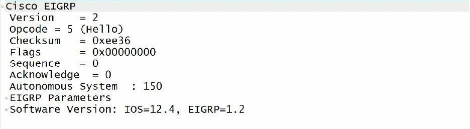 图 36.2 -- 对EIGRP数据包头部的抓包
在该EIGRP数据包头部,4位的OPCode字段被用于指明该EIGRP数据包类型或报文。EIGRP使用到不同的报文或数据包类型,它们是Hello数据包(Hello packets)、确认数据包(Acknowledgment packets)、更新数据包(Update packets)、查询数据包(Query packets)、应答数据包(Reply packets)以及请求数据包(Request packets),共计6种报文或数据包类型。将在随后的小节对这些类型的数据包进行说明。
Hello数据包
Hello Packets
在某台路由器上对某个特定网络开启了增强的IGRP后,其就会发送Hello数据包(Enhanced IGRP sends Hello packets once it has been enabled on a router for a particular network)。这些报文被用于邻居的识别,同时邻居一经识别后,Hello报文就用于在邻居间作为一种保持活动机制,发挥作用(these messages are used to identify neighbours and, once identified, serve or function as a keepalive mechanism between neighbours)。EIGRP的邻居发现与维护机制,将在本课程模块的后面进行说明。
EIGRP的Hello数据包,是发送到链路本地多播组地址(the Link Local Multicast group address)224.0.0.10上的。由EIGRP发出的Hello数据包,是不需要发出确认数据包来确认其已收到的(Hello packets sent by EIGRP do not require an Acknowledgment to be sent confirming that they were received)。因为Hello数据包不需要显式的确认,所以它们被分类为不可靠的EIGRP数据包(Hello packets are classified as unreliable EIGRP packets)。EIGRP Hello数据包的OPCode为5。
确认数据包
Acknowledgment Packets
EIGRP确认数据包,就是一个不包含数据的EIGRP Hello数据包。EIGRP使用确认数据包来对EIGRP数据包的可靠送达进行确认。这些确认数据包(the ACK packets)总是发送到一个单播地址(a Unicast address), 该地址就是可靠数据包发送方的源地址(the source address of the sender of the reliable packet),而并不是EIGRP的多播组地址了。此外,确认数据包将总是会包含一个非零的确认编号(a non-zero acknowledgment number)。确认数据包使用了Hello数据包相同的OPCode, 因为其本来就是一个不包含任何信息的Hello数据包。其OPCode为5。
更新数据包
Update Packets
增强IGRP的更新数据包被用于传送目标的可达性(used to convey reachability of destinations)。也就是说,更新数据包包含了EIGRP的路由更新。在发现了一个新的邻居时,就会通过单播发出更新数据包(往该新的邻居),如此新的邻居就能够建立起自己的EIGRP拓扑表了。在其它情况,比如某链路的开销改变时,就会经由多播发出更新数据包。重要的是记住更新数据包都是可靠地传输的,且总是要求显式的确认。分配给更新数据包的OPCode是1。下图36.3演示了一个EIGRP的更新数据包:
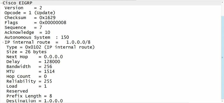 图 36.3 -- EIGRP的更新数据包
注意: 并不要求对EIGRP各种数据包中的所包含的信息有深入了解。
查询数据包
Query Packets
增强IGRP的查询数据包是多播的,并被用于请求可靠的路由信息。EIGRP的查询数据包是在某条路由不可用,但该路由器却需要为快速收敛,而需要就该路由的状态进行询问时,所发送给其邻居的数据包。如发出查询数据包的路由器未能从其某些邻居收到响应,那么其就会再度向那些未响应的邻居发出一次查询。如在16次尝试后都没有响应,那么该EIGRP邻居关系将被重置。本课程模块后面将对此概念进行更为深入的说明。分配给EIGRP查询数据包的OPCode为3。
应答数据包
Reply Packets
增强IGRP的应答数据包是作为对查询数据包的响应发送的。应答数据包用于可靠地响应某个查询数据包。应答数据包是到查询发起方的单播数据包。分配给EIGRP应答数据包的OPCode为4。
请求数据包
Request Packets
增强IGRP的请求数据包,用于从一个或多个邻居处获取特定信息,且是在路由服务器应用中用到的(used in route server applications)。这些数据包既可通过单播、也可通过多播进行发送,但它们总是以不可靠方式传输。也就是说,它们无需显式确认。
注意: 尽管这里的Hello数据包和确认数据包是作为两种独立的数据包类型的,但重要的是记住在某些课本中,EIGRP的Hello数据包与确认数据包被认为是同一中类型的数据包。这是因为,正如在本小节中指出的那样,确认数据包就是不包含数据的Hello数据包。
命令debug eigrp packets,可用于打印出本小节中所讲到的各种不同EIGRP数据包的实时调试信息。要知道此命令还包括了一些这里并没有说到的其它数据包,因为这些其它类型数据包超出了当前CCNA考试要求。下面的输出对此命令的用法进行了演示:
R1#debug eigrp packets ?
  SIAquery  EIGRP SIA-Query packets
  SIAreply  EIGRP SIA-Reply packets
  ack       EIGRP ack packets
  hello     EIGRP hello packets
  ipxsap    EIGRP ipxsap packets
  probe     EIGRP probe packets
  query     EIGRP query packets
  reply     EIGRP reply packets
  request   EIGRP request packets
  retry     EIGRP retransmissions
  stub      EIGRP stub packets
  terse     Display all EIGRP packets except Hellos
  update    EIGRP update packets
  verbose   Display all EIGRP packets
  <cr>
而show ip eigrp traffic命令,则是用于对本地路由器所发送及接收到的EIGRP数据包的数量进行查看的命令。该命令同时还是一个强大的故障排除工具。比如假设某路由器在发出Hello数据包,却并未收到任何回复,这可能表明其尚未配置好预期的邻居,或者甚至有可能某个确认数据包阻塞了EIGRP数据包(For example, if the router is sending out Hello packets but is not receiving any back, this could indicate that the intended neighbour is not configured, or even that an ACK may be blocking EIGRP packets)。下面的输出对此命令进行了演示:
R2#show ip eigrp traffic
IP-EIGRP Traffic Statistics for AS 150
    Hellos sent/received: 21918/21922
    Updates sent/received: 10/6
    Queries sent/received: 1/0
    Replies sent/received: 0/1
    Acks sent/received: 6/10
    SIA-Queries sent/received: 0/0
    SIA-Replies sent/received: 0/0
    Hello Process ID: 178
    PDM Process ID: 154
    IP Socket queue: 0/2000/2/0 (current/max/highest/drops)
    Eigrp input queue: 0/2000/2/0 (current/max/highest/drops)
下表36.1对本小节中讲到的这些EIGRP的数据包进行了总结,以及各自是否以可靠或不可靠方式进行发送:
表 36.1 -- EIGRP数据包总结
| 报文类型 | 说明 | 发送方式 |
|---|---|---|
| Hello | 用于邻居发现、维护及保持存活 | 不可靠 |
| 确认数据包(Acknowledgment) | 用于对信息接收的确认 | 不可靠 |
| 更新数据包(Update) | 用于传达路由信息 | 可靠的 |
| 查询数据包(Query) | 用于请求指定的路由信息 | 可靠的 |
| 应答数据包(Reply) | 用于对查询数据包的响应 | 可靠的 |
| 请求数据包(Request) | 用于路由服务器应用中的信息请求 | 不可靠 |
EIGRP的邻居发现与邻居维护
EIGRP Neighbour Discovery and Maintenance
可将增强的IGRP配置为动态地发现相邻路由器(这是默认选项)(discover neighbouring routers dynamically(default)),或者经由管理员手动配置来发现相邻路由器。下面的小节将对这两种方式,以及其它有关EIGRP邻居相关话题,进行讨论。
动态的邻居发现
Dynamic Neighbour Discovery
动态邻居发现,是通过往目的多播组地址(the destination Multicast group address)224.0.0.10, 发送EIGRP的Hello数据包完成的。动态邻居发现,又是紧跟着在路由器配置EIGRP时network命令的执行,而完成的。此外,如早先指出的那样,EIGRP数据包直接透过IP、使用协议编号88发送。下图36.4对此基本的EIGRP邻居发现与路由交换过程,进行了演示:
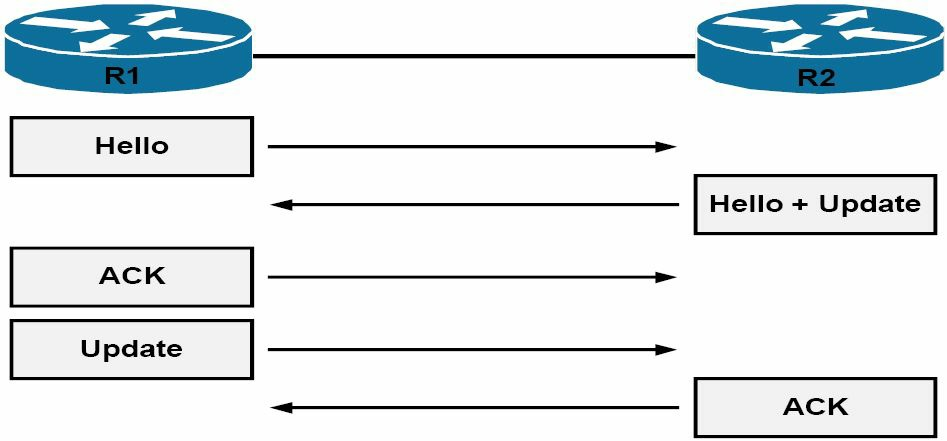 图 36.4 -- EIGRP的邻居发现与路由交换,EIGRP Neighbour Discovery and Route Exchange
参考图36.4, 在初始化时,这些EIGRP邻居便发出Hello数据包,以发现其它邻居(Referencing Figure 36.4, upon initialisation, the EIGRP neighbours send Hello packets to discover other neighbours)。随后邻居们就通过完整更新,就其整个路由表进行交换。这些更新包含了所有已知路由信息。因为更新包是可靠发送的,接收方就必须对其进行显式确认。
在邻居们完成它们的路由信息交换后,还将持续交换Hello数据包,以维护邻居关系。此外,这些EIGRP邻居路由器以后就将仅发送增量更新了,通过增量更新来将其状态或路由变化,通告给它们的邻居们。它们再也不会发送完整的更新给邻居们了。
这里重要的是要明白仅简单地在两台或多台路由器上开启EIGRP,并不能确保邻居关系的建立。而是还需一些参数必须要匹配,这样这些路由器才能成为邻居。在以下几种情况下,就不能建立EIGRP邻居关系:
- EIGRP认证参数不匹配(在有配置时),Mismatched EIGRP authentication parameters(if configured)
- EIGRP的那些K值不一致,Mismatched EIGRP K values
- EIGRP自治系统编号不一致,Mismatched EIGRP autonomous system number
- 在EIGRP邻居关系中,使用了接口的第二地址,Using secondary addresses for EIGRP neighbour relationships
- 邻居并不位于同一子网中,the neighbours are not on a common subnet
尽管show ip eigrp neighbours命令在动态与静态配置的邻居间没有区别,但**show ip eigrp interfaces detail <name> 命令却可以用于对路由器接口是否在发出多播数据包来发现和维护邻居关系,进行检查**。下面演示了在一台开启了动态邻居发现的路由器上该命令的输出:
R2#show ip eigrp interfaces detail FastEthernet0/0
IP-EIGRP interfaces for process 150
                      Xmit Queue   Mean   Pacing Time    Multicast      Pending
Interface      Peers  Un/Reliable  SRTT   Un/Reliable    Flow Timer     Routes
Fa0/0            1        0/0        1        0/1            50             0

  Hello interval is 5 sec
  Next xmit serial <none>
  Un/reliable mcasts: 0/2  Un/reliable ucasts: 2/2
  Mcast exceptions: 0  CR packets: 0  ACKs suppressed: 0
  Retransmissions sent: 1  Out-of-sequence rcvd: 0
  Authentication mode is not set
  Use multicast
注意:
show ip eigrp neighbours命令将在后面讲到。在查看show ip eigrp interfaces detail <name>命令的输出时,要注意因为EIGRP同时用到多播及单播数据包(both Multicast and Unicast packets),所以该命令的计数器将包含两种类型数据包的数值,如上面输出所示。
静态的邻居发现
Static Neighbour Discovery
与动态EIGRP邻居发现过程不同,静态EIGRP邻居关系需要在路由器上手动配置邻居。在配置好静态EIGRP邻居后,本地路由器就使用单播邻居地址,往这些路由器发送数据包。
在EIGRP网络中,静态邻居关系的使用是十分罕见的。这主要是因为手动邻居配置在大型网络中无法适应其规模。但重要的是弄明白为何思科IOS软件中还是有此选项,以及在什么情况下可以运用到此特性。使用静态邻居配置的一个主要,就是在那些没有广播或多播数据包原生支持的传输介质,比如帧中继上,部署EIGRP的情况下(A prime example of when static neighbour configuration could be used would be in a situation where EIGRP is being deployed across media that does not natively support Broadcast or Multicast packets, such as Frame Relay)。
另一实例就是在譬如以太网这样的多路访问网络上,仅有少数几台开启了EIGRP的路由器时,为了防止发送不必要的EIGRP数据包的情形。在此情况下,除开基本的EIGRP配置,还必须在本地路由器上对所有静态EIGRP邻居配置neighbour命令。如果一台路由器被配置为使用单播(静态),而其它路由器又被配置为使用多播(动态),那么这些开启了EIGRP的路由器是不会建立邻接关系的(EIGRP-enabled routers will not establish an adjacency if one router is configured to use Unicast(static) while another uses Multicast(dynamic))。
在思科IOS软件中,静态EIGRP的邻居,是通过使用路由器配置命令(router configuration command)neighbour <address> <interface>进行配置的。记住这只是简单的对基础EIGRP配置的补充(this is simply in addition to the basic EIGRP configuration)。下图36.5中给出的简单网络拓扑,将用于静态EIGRP邻居的演示和验证。
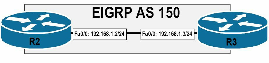 图 36.5 -- 配置静态的EIGRP邻居
参考图36.5中所给出的拓扑,路由器R2将作如下配置:
R2(config)#router eigrp 150
R2(config-router)#network 192.168.1.0 0.0.0.255
R2(config-router)#neighbor 192.168.1.3 FastEthernet0/0
R2(config-router)#no auto-summary
R2(config-router)#exit
而应用于路由器R3上的配置则如下:
R3(config)#router eigrp 150
R3(config-router)#network 192.168.1.0 0.0.0.255
R3(config-router)#neighbor 192.168.1.2 FastEthernet0/0
R3(config-router)#no auto-summary
R3(config-router)#exit
可使用show ip eigrp interfaces detail <name>命令,对路由器接口使用多播(动态),还是使用单播(静态)数据包来进行邻居发现与维护进行判断。下面的输出对此进行了演示:
R2#show ip eigrp interfaces detail FastEthernet0/0
IP-EIGRP interfaces for process 150
                      Xmit Queue   Mean   Pacing Time    Multicast      Pending
Interface      Peers  Un/Reliable  SRTT   Un/Reliable    Flow Timer     Routes
Fa0/0            1        0/0        2        0/1            50             0

  Hello interval is 5 sec
  Next xmit serial <none>
  Un/reliable mcasts: 0/1  Un/reliable ucasts: 3/8
  Mcast exceptions: 1  CR packets: 1  ACKs suppressed: 2
  Retransmissions sent: 1  Out-of-sequence rcvd: 0
  Authentication mode is not set
  Use unicast
此外,可使用show ip eigrp neighbours [detail]命令来判断EIGRP邻居的类型。在本课程模块的后面将对此命令进行详细讲解。
EIGRP的Hello及保持计时器
EIGRP Hello and Hold Timers
增强的IGRP对不同传输介质,使用不同的Hello及保持计数器。Hello计时器被用于确定发送EIGRP Hello数据包的时间间隔。保持计数器则用于确定下路由器在认为其某个邻居宕机前,要经历的时间(the Hold timer is used to determine the time that will elapse before a router consider an EIGRP neighbour as down)。默认保持时间是Hello间隔的3倍。
在广播网络、点对点串行网络、点对点子接口网络及高于T1线路速率的多点电路网络上,增强的IGRP每5秒发送一次Hello数据包(Enhanced IGRP sends Hello packets every 5 seconds on Broadcast, Point-to-Point Serial, Point-to-Point subinterfaces, and Multipoint circuits greater than T1 speed)。而默认的保持时间就是15秒。在其它链路类型网络上,包括速率低于T1线路的低带宽的WAN链路,EIGRP每60秒发送Hello数据包。在这些链路上的邻居关系保持时间也是Hello间隔的3倍,也就是180秒。
在那些相邻路由器上,不必为了形成邻居关系而要求EIGRP计时器数值保持一致(Enhanced IGRP timer value do not have to be the same on neighbouring routers in order for a neighbour relationship to be established)。此外,对于保持时间是Hello间隔的3倍这一点,也没有强制性要求。这只是一种建议的做法(a recommended guideline),因此可在思科IOS软件中进行手动修改。可使用接口配置命令ip hello-interval eigrp <ASN> <secs>,对EIGRP的Hello时间进行调整,使用借口配置命令ip hold-time eigrp <ASN> <secs>,对EIGRP的保持时间进行调整。
掌握EIGRP中Hello计时器及保持计时器的用法,是重要的。保持时间是在EIGRP的Hello数据包中通告的,同时Hello时间值告诉本地路由器往其邻居发送Hello数据包的频率。而保持时间,则告诉其邻居路由器,在等待多长时间后,就可以宣布其已“死亡”(the hold time, on the other hand, tells the neighbour router(s) of the local router how long to wait before declaring the local router "dead")。下图36.6演示了EIGRP的Hello数据包,以及保持时间字段(the Hold Time field):
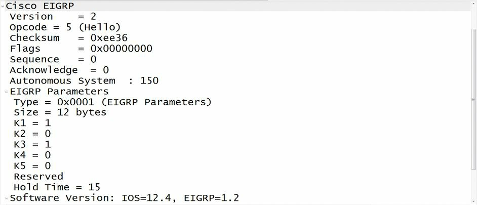 图 36.6 -- EIGRP Hello 数据包中的EIGRP保持时间
参考图36.6, 除开其它方面,该EIGRP Hello数据包(OPCode 5)包含了所配置的保持时间数值。图36.6中所显示的值15, 是一个使用接口配置命令ip hold-time eigrp <ASN> <secs>所配置的非默认数值。重要的是记住,在Hello数据包中,是不包含Hello时间间隔的。但可使用show ip eigrp interfaces detail <name>命令,查看到所配置的Hello时间。下面演示了此命令所打印出的信息:
R2#show ip eigrp interfaces detail FastEthernet0/0
IP-EIGRP interfaces for process 150
                      Xmit Queue   Mean   Pacing Time    Multicast      Pending
Interface      Peers  Un/Reliable  SRTT   Un/Reliable    Flow Timer     Routes
Fa0/0            1        0/0        7        0/1            50             0

  Hello interval is 5 sec
  Next xmit serial <none>
  Un/reliable mcasts: 0/1  Un/reliable ucasts: 2/5
  Mcast exceptions: 1  CR packets: 1  ACKs suppressed: 0
  Retransmissions sent: 1  Out-of-sequence rcvd: 0
  Authentication mode is not set
  Use multicast
调整默认EIGRP计时器数值的最常见原因,就是要加速路由协议的收敛。比如在一条低速WAN链路上,180秒的保持时间将是一个在EIGRP宣告某台邻居路由器宕机之前,所要等待的相当长的时间。相反,在某些情形中,为了确保得到一个稳定的路由拓扑,就可能有必要在某些高速链路上增加EIGRP计时器数值。在部署某种活动粘滞路由方案(a solution for Stuck-In-Active routes)时,这是常见的做法。本课程模块后面或详细讲解活动粘滞路由。
EIGRP的邻居表
EIGRP Neighbour Table
运行EIGRP的路由器使用EIGRP邻居表,来维护有关EIGRP邻居的状态信息。在学习到新近发现的邻居时,该邻居的地址和接口就被记录下来。这对于动态发现的邻居与静态定义的邻居,都是适用的。对每种协议相关模组(Protocol-Dependent Module, PDM,Wikipedia上的PDM),都有着一个唯一的EIGRP邻居表。
在某个EIGRP邻居发出了一个Hello数据包时,其就通告出一个保持时间,此保持时间就是某台路由器将一个邻居视为可达且运作中的时间长短。在某台路由器收到一个Hello数据包后,该保持时间就开始减少,直到计数到0。此时就会收到另一个Hello数据包,同时保持时间又开始从头减少,同时该过程继续重复。而如果在保持时间内未能收到Hello数据包,那么保持时间就超时了(到0)。在保持时间超时后,弥散更新算法就被告知拓扑的变化,同时EIGRP宣告该邻居已宕机。路由器将打印并记录如下的一条类似消息:
%DUAL-5-NBRCHANGE: IP-EIGRP(0) 1: Neighbor 10.1.1.2 (Serial0/0) is down: holding time expired
EIGRP邻居表条目还包含了可靠传输协议(the Reliable Transport Protocol, RTP)所需要的信息。EIGRP使用可靠传输协议来确保更新、查询及应答数据包的可靠发送。此外还使用了顺序编号来匹配数据包与确认。EIGRP邻居表条目中记录了从该邻居收到的最后一个顺序编号,以便检测出那些次序被打乱了的数据包(In addtion, sequence numbers are also used to match acknowledgments with data packets. The last sequence number received from the neighbour is recorded in order to detect out-of-order packets)。这样做确保了可靠的数据包送达。
注意: 本课程模块后面详细讲到了RTP。
邻居表包含了每个邻居的一个在可能需要重传时,用于对数据包进行排队的传输清单。此外,在邻居数据结构中还有着一些往返计时器,使用这些计时器来估算出最优重传间隔(the neighbour table includes a transmission list that is used to queue packets for possible retransmission on a per-neighbour basis. Additionally, round-trip timers are kept in the neighbour data structure to estimate an optimal retransmission interval)。所有这些信息都在show ip eigrp neighbours命令的输出中有打印出来。如下面所示:
R2#show ip eigrp neighbors
IP-EIGRP neighbors for process 150
H   Address      Interface  Hold   Uptime     SRTT    RTO    Q     Seq
                            (sec)             (ms)           Cnt   Num
0   192.168.1.3  Fa0/0      14     00:43:08    2      200    0     12
对此命令所打印出的信息的掌握,是相当重要的,既是作为对一项核心EIGRP组件能力进行演示的基础,同时也是对EIGRP故障进行排除的基础(It is important to understand the information printed by this command, both as a basis for demonstrating competency on a core EIGRP component and for troubleshooting EIGRP issues)。下表36.2对此命令输出中所包含的那些字段,进行了列出和说明:
表 36.2 -- EIGRP邻居表的各个字段
| 字段 | 说明 |
|---|---|
| H | 邻居清单(编号),以所学习到的先后顺序,以“0”开始 |
| Address | 邻居的IP地址 |
| Interface | 经由其学习到邻居的那个接口(the interface via which the neighbour is learned) |
| Hold | 邻居的保持计数器;在其到0时,邻居就已宕机 |
| Uptime | 邻居关系已建立了多长时间 |
| SRTT | 平滑往返时间(Smooth Round-Trip Time), 发送并接收到一个可靠EIGRP数据包所花费的时间 |
| RTO | 重传超时(Retransmission Timeout), 在未收到一次确认时,路由器重新传送EIGRP可靠数据包所要等待的时间 |
| Q Cnt | 等待发送中的EIGRP数据包(Update, Query and Reply)数量 |
| Sequence Number | 从该邻居所接收到的上一个EIGRP可靠数据包的顺序编号,用以确保自该邻居接收到的数据包是有序的 |
尽管show ip eigrp neighbours命令打印出有关已知EIGRP邻居信息,其在动态发现的邻居和手动配置的邻居上是没有区别的。比如,在路由器R2上的该show ip eigrp neighbours命令的输出表明该路由器有着两个EIGRP邻居关系。在此配置下,其中一个是静态配置的邻居,而另一个则是动态发现的。可以看出,从下面的输出是没法判断出哪个是哪个的:
R2#show ip eigrp neighbors
IP-EIGRP neighbors for process 150
H   Address      Interface  Hold   Uptime     SRTT    RTO    Q     Seq
                            (sec)             (ms)           Cnt   Num
1   150.2.2.2    Se0/0      13     00:00:48    153    918    0     4
0   192.168.1.3  Fa0/0      10     08:33:23    1      200    0     20
在路由器同时有着动态发现与静态配置的邻居关系环境中,可以使用show ip eigrp neighbours detail命令,来判断出哪个邻居是静态配置的,哪个是动态发现的,如下面所示:
R2#show ip eigrp neighbors
IP-EIGRP neighbors for process 150
H   Address      Interface  Hold   Uptime     SRTT    RTO    Q     Seq
                            (sec)             (ms)           Cnt   Num
1   150.2.2.2    Se0/0      11     00:04:22    153    918    0     4
   Version 12.3/1.2, Retrans: 0, Retries: 0, Prefixes: 1
0   192.168.1.3  Fa0/0      10     08:33:23    1      200    0     20
   Static neighbour
   Version 12.4/1.2, Retrans: 0, Retries: 0, Prefixes: 1
参考上面的输出,邻居192.168.1.3就是手动配置的邻居,而邻居150.2.2.2则是动态发现的邻居了。还可以通过使用show ip eigrp neighbours static <interface>,来查看到那些静态邻居,如下所示:
R2#show ip eigrp neighbors static FastEthernet0/0
IP-EIGRP neighbors for process 150
Static Address           Interface
192.168.1.3              FastEthernet0/0
可靠传输协议
Reliable Transport Protocol
增强的IGRP需要自己的传输协议,来确保数据包的可靠送达。EIGRP使用可靠传输协议,来确保更新(Update)、查询(Query)及应答(Reply)数据包的可靠发送。顺序编号的使用,还确保了EIGRP数据包的有序接收。
当可靠EIGRP数据包发送到某个邻居时,发送路由器期望从接收路由器收到一个表明该数据包已收到的确认。在使用可靠传输协议时,EIGRP维护着一个未确认数据包的传输窗口(a transport window of one unacknowledged packet), 这就意味着所发出的所有可靠数据包,都需要进行确认,之后才能发出下一个数据包。发送方路由器将对未收到确认的可靠数据包进行重传,直到其收到一个确认。
但重要的是需注意到,未经确认的数据包只会重传16次。如在16次重传后仍没有确认,EIGRP将对该邻居关系进行重置。可靠传输协议使用到多播及单播数据包。在诸如以太网这样的广播多路访问网络,EIGRP就会向网段上的每台路由器发送多播数据包,而不是单个数据包(单播)(On Broadcast Multi-Access networks such as Ethernet, EIGRP uses Multicast packets instead of sending an individual packet(Unicast) to each router on the segment)。但在没有从多路访问网段上一台或更多的邻居收到响应时,还是会用单播发送数据包。下面结合图36.7中的图表,对此进行了说明:
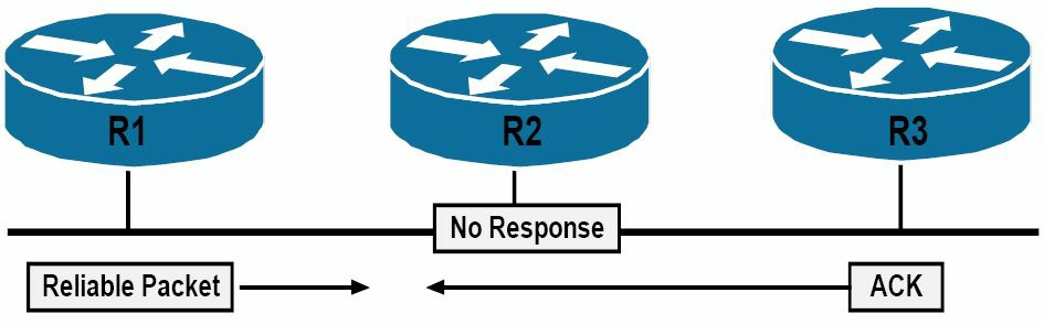 图 36.7 -- EIGRP可靠传输协议的运作
在图36.7中,路由器R1、R2与R3位于多路访问网段上的同一子网中。在给定的传输介质下,EIGRP将使用多播,在这些路由器直接发送可靠数据包。这里假定,比如路由器R1发出了一个需要确认的数据包给路由器R2和R3。随后R1就等待来自R2和R3收到此数据包的确认。
假设路由器R3响应了,R2却无法对此数据包进行响应。在EIGRP维护了一个未确认数据包传输窗口的情况下,就是说每个发出的单独可靠数据包,在发送下一个可靠数据包之前,都必须要邻居路由器进行显式的确认,而由于路由器R1将无法在收到来自R2的确认前,发出数据包,这样就在该多路访问网段上出现了一个可能的问题。因此路由器R3就间接受到R2上故障的影响了。
为了避免这种坑,路由器R1将等待连接到该多路访问网段上的以太网接口的多播流计时器超时(To avoid this potential pitfall, R1 will wait for the Multicast Flow Timer(MFT) on the Ethernet interface connected to the Multi-access segment to expire)。多播流计时器,或简单的说就是流计时器(the Flow Timer),是发送方路由器等待自某个组成员的确认数据包的最长时间。在该计数器超时后,路由器R1将以多播方式,发出一个特殊的名为顺序TLV的EIGRP数据包(when the timer expires, R1 will Multicast a special EIGRP packet called a Sequence TLV)。此数据包列出了路由器R2(也就是例外的那台路由器,the offender),且表明其是一个顺序错乱的多播数据包(this packet lists R2(the offender) and indicates an out-of-order Multicast packet)。而因为路由器R3未被列入到该数据包,所以其就进入到条件接收模式(the Conditional Receive(CR) mode), 并继续侦听多播数据包。路由器R1此时就使用单播,将该数据包重传给R2。重传超时(the Retransmission Timeout, RTO)表示等待那个单播数据包的确认的时间。如在总共16次尝试后,仍没有来自路由器R2的响应,EIGRP将重置该邻居。
注意: 当前的CCNA考试不要求对MFT及RTO有深入了解。
各种度量值、弥散更新算法及拓扑表
Metrics, DUAL, and the Topology Table
在部署EIGRP时,对于路由被真正放入到IP路由表中之前,所用到的EIGRP本身及为其所用到的方方面面的概念、方法及数据结构等的掌握,是重要的。在本小节中,将学到有关EIGRP的综合度量值及其计算方式。还将学习影响度量值计算,及对计算出的度量值进行调整的不同方式(when implementing EIGRP, it is important to understand the various aspects used within and by the protocol before routes are actually placed into the IP routing table. In this section, you will learn about the EIGRP composite metric and how it is calculated. You will also learn about the different ways to influence metric calculation, as well as to adjust the calculated metric)。
在那之后,将学习到弥散更新算法(the Diffusing Update Algorithm, DUAL)与EIGRP的拓扑表。此小节包括了一个有关如何在一台运行着EIGRP的路由器上,将所有这些信息进行配合,以最终产生出IP路由表的讨论。
EIGRP综合度量值的计算
EIGRP Composite Metric Calculation
增强的EIGRP使用了一种综合度量值(a composite metric), 该度量值包含了以不同的K值所表示的不同变量(Enhanced IGRP uses a composite metric, which includes different variables referred to as the K values)。这些K值是一些常量,用于赋予路径的不同方面以不同的权重,这些路径的不同方面,都可能包含在该综合EIGRP度量值中。这些K值的默认值为 K1=K3=1, K2=K4=K5=0。也就是说,K1与K3被默认被设置为1, 同时K2、K4和K5默认被设置为0。
假定在这些默认的K值下,那么完整的EIGRP度量值就可以使用下面的数学公式算出来:
[K1*带宽 + (K2*带宽)/(256-负载) + K3*延迟] * [K5/(可靠性+K4)]
但在仅有K1和K3有着默认的正值的情况下,默认的EIGRP度量值是由下面的数学公式计算出来的:
[(10^7/路径上的最低带宽) + (所有延迟总和)] x 256
这实际上就是说,EIGRP使用了到目的网络的路径上的最小带宽,以及总的累积延迟,来计算理由度量值。不过思科IOS软件允许管理员将其它K值设置为非零值,以将其它变量结合到该综合度量值中。通过使用路由器配置命令metric weights [tos] k1 k2 k3 k4 k5,就可完成此操作。
在使用metric weights命令时,[tos]表示服务类型(Type of Service)。尽管思科IOS软件显示可以使用任何0到8之间的数值,但在撰写本手册时,该字段([tos])当前却只能被设置为0。而这些K值,就可以被设置为0到255之间的任何数值。通过执行show ip protocols命令,就可查看默认的这些EIGRP K值。下面的输出对此进行了演示:
R2#show ip protocols
Routing Protocol is “eigrp 150”
  Outgoing update filter list for all interfaces is not set
  Incoming update filter list for all interfaces is not set
  Default networks flagged in outgoing updates
  Default networks accepted from incoming updates
  EIGRP metric weight K1=1, K2=0, K3=1, K4=0, K5=0
  EIGRP maximum hopcount 100
  EIGRP maximum metric variance 1
  Redistributing: eigrp 150
  EIGRP NSF-aware route hold timer is 240s
  Automatic network summarization is not in effect
  Maximum path: 4
  Routing for Networks:
    192.168.1.0
  Routing Information Sources:
    Gateway         Distance        Last Update
    192.168.1.3     90              00:00:15
  Distance: internal 90 external 170
在对这些EIGRP的K值进行调整时,重要的是记住在EIGRP域中的所有路由器上,都要配置上同样的这些数值。如这些K值不匹配,那么EIGRP的邻居关系就不会建立。
注意: 不建议对这些默认的K值进行调整。对这些K值的调整,只应在那些对网络中这类行为造成的后果有扎实了解老练的高级工程师的指导下,或在思科公司技术支持中心的建议下完成。
使用接口带宽来影响EIGRP的度量值
Using Interface Bandwidth to Influence EIGRP Metric Calculation
可通过使用bandwidth命令对指定到那些单个接口的默认带宽进行调整,从而直接对EIGRP度量值计算施加影响。通过此命令指定的带宽,是以千位(Kilobits)计的。在EIGRP的度量值计算中,带宽也是以千位计的。下图36.8演示了一个由两台路由器通过两条带宽为1544Kbps, 的串行(T1)链路连接所组成的网络。
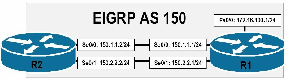 图 36.8 -- EIGRP度量值的带宽修改
参考图36.8中的图示,因为路由器R1与R2之间两条链路的带宽(及延迟)是相等的,所以从路由器R2到子网172.16.100.0/24将同时继承到这两条路径的相同EIGRP度量值(because of the equal bandwidth (and delay) values of the links between R1 and R2, the same EIGRP metric will be derived for both paths from R2 to the 172.16.100.0/24 subnet)。EIGRP将在这两条链路之间进行流量负载均衡,如下面路由器R2上的输出所示:
R2#show ip route 172.16.100.0 255.255.255.0
Routing entry for 172.16.100.0/24
  Known via “eigrp 150”, distance 90, metric 2172416, type internal
  Redistributing via eigrp 150
  Last update from 150.2.2.1 on Serial0/1, 00:48:09 ago
  Routing Descriptor Blocks:
    150.2.2.1, from 150.2.2.1, 00:48:09 ago, via Serial0/1
      Route metric is 2172416, traffic share count is 1
      Total delay is 20100 microseconds, minimum bandwidth is 1544 Kbit
      Reliability 255/255, minimum MTU 1500 bytes
      Loading 1/255, Hops 1
  * 150.1.1.1, from 150.1.1.1, 00:48:09 ago, via Serial0/0
      Route metric is 2172416, traffic share count is 1
      Total delay is 20100 microseconds, minimum bandwidth is 1544 Kbit
      Reliability 255/255, minimum MTU 1500 bytes
      Loading 1/255, Hops
对两条链路中的任何一条的带宽进行调整,都会直接影响到EIGRP对到目的网络路径的度量值计算。这样的操作,可用于更为大型网络中路径的控制(也就是基于管理员定义的数值与配置,对流量所要采行的路径进行控制)(Such actions can be used for path control within larger networks(i.e., controlling the path that traffic takes based on administrator-defined values and configurations))。比如这里要令到EIGRP优先使用Serial0/0作为前往目的网络的主要路径,而将Serial0/1作为到目的网络的备份路径,就要采取两种操作之一。
第一种操作,就是可以增加Serial0/0上的带宽值,造成该路径的一个更好(更低)的度量值。那么第二种方法,就是可以降低Serial0/1上的带宽值,造成该路径的一个更差(更高)的度量值。两种选项都是可接受的,同时都将达成所需的结果。下面的输出演示了如何将Serial0/0上的默认带宽进行降低,从而有效地确保Serial0/0作为路由器R2及172.16.100.0/24网络之间的主要路径。
R2(config)#interface Serial0/1
R2(config-if)#bandwidth 1024
R2(config-if)#exit
注意: 如同在第1天指出的,该配置并不意味着接口
Serial0/1上仅容许1024Kbps速率的流量通过该接口(As stated in Day 1, this configuration does not mean thatSerial0/1is now capable of only 1024Kbps of throughput through this interface)。
该配置的结果就是接口Serial0/0成为路由器R2到达目的网络172.16.100.0/24网络的主要路径。这在下面的输出中有所演示:
R2#show ip route 172.16.100.0 255.255.255.0
Routing entry for 172.16.100.0/24
  Known via “eigrp 150”, distance 90, metric 2172416, type internal
  Redistributing via eigrp 150
  Last update from 150.1.1.1 on Serial0/0, 00:01:55 ago
  Routing Descriptor Blocks:
  * 150.1.1.1, from 150.1.1.1, 00:01:55 ago, via Serial0/0
      Route metric is 2172416, traffic share count is 1
      Total delay is 20100 microseconds, minimum bandwidth is 1544 Kbit
      Reliability 255/255, minimum MTU 1500 bytes
      Loading 1/255, Hops 1
注意: 这里星号(the asterisk,
*)指向的接口,就是下一数据包要发送出去的接口。而在路由表中有着多个开销相等的路由时,星号的位置就会在这些开销相等的路径之间轮转。
在将EIGRP作为路由协议时,尽管经由Serial0/1接口的路径未被安装到路由表中, 重要的是记住该路径并未被完全忽略掉(Although the path via the Serial0/1 interface is not installed into the routing table, when using EIGRP as the routing protocol, it is important to remember that this path is not completely ignored)。而是该路径被存储在EIGRP的拓扑表中,EIGRP的拓扑表包含了到那些远端目网络的主要及替代(备份)路径。本课程模块后面将对EIGRP的拓扑表予以讲解。
注意: 默认在开启了EIGRP时,其可能会用到高达接口带宽的50%来发送EIGRP本身的数据包(EIGRP是一种非常话痨的协议,所以其在可能的带宽使用上进行了限制,EIGRP is a very chatty protocol, so it limits itself in possible bandwidth usage)。EIGRP是基于接口配置命令
bandwidth,来判断带宽数量的。因此在对接口带宽数值进行调整时,就要记住这点。而该默认设置,可使用接口配置命令**ip bandwidth-percent eigrp [ASN] [percentage]**,进行修改。
总的来说,在应用带宽命令bandwidth对EIGRP的度量值计算施加影响时,重要的是记住,EIGRP会使用到目的网络路径上的最小带宽,以及延迟的累计值,来计算路由度量值(EIGRP uses the minimum bandwidth on the path to a destination network, along with the cumulative delay, to compute routing metrics)。同时还要对网络拓扑有牢固掌握,以对在何处使用bandwidth命令,从而实现对EIGRP度量值计算的影响。但在真实世界中,对EIGRP度量值施加影响的首选方法,不是修改带宽,而是修改延迟。
运用接口的延迟来对EIGRP的度量值计算进行影响
Using Interface Delay to Influence EIGRP Metric Calculation
接口延迟数值,是用微秒来表示的。但在EIGRP度量值计算中用到的延迟数值,是以10微秒计的(in tens of microseconds)。因此,为了计算出EIGRP的度量值,接口上的延迟数值,就必须除以10。下面的表36.3对思科IOS软件中使用到的默认接口带宽及延迟数值,进行了演示:
表 36.3 -- 默认的接口带宽与延迟数值
| 接口类型 | 带宽(Kilobits) | 延迟(Microseconds, us) |
|---|---|---|
| 以太网(Ethernet) | 10000 | 1000 |
| 快速以太网(FastEthernet) | 100000 | 100 |
| 千兆以太网(GigabitEthernet) | 1000000 | 10 |
| 万兆以太网(Ten-GigabitEthernet) | 10000000 | 10 |
| 串行线路(T1) | 1544 | 20000 |
| 串行线路(E1) | 2048 | 20000 |
| 串行线路(T3) | 44736 | 200 |
| 串行线路(E3) | 34010 | 200 |
在对接口的带宽及延迟数值进行计算时,重要的是记住对接口带宽的调整并不会自动地调整到接口的延迟,相反也是这样。这两个数值是相互独立的。比如,下面的输出展示了一个快速以太网接口的默认带宽及延迟数值:
R2#show interfaces FastEthernet0/0
FastEthernet0/0 is up, line protocol is up
  Hardware is AmdFE, address is 0013.1986.0a20 (bia 0013.1986.0a20)
  Internet address is 192.168.1.2/24
  MTU 1500 bytes, BW 100000 Kbit/sec, DLY 100 usec,
     reliability 255/255, txload 1/255, rxload 1/255
...
[Truncated Output]
为对此概念进行强化,下面使用接口配置命令bandwidth,将该快速以太网接口的带宽调整为1544Kbps:
R2(config)#interface FastEthernet0/0
R2(config-if)#bandwidth 1544
R2(config-if)#exit
此时显示在show interfaces命令的输出中的带宽数值,反应了该已应用下去的配置,但默认的接口延迟数值却仍然保持原来的大小,如下面的输出所示:
R2#show interfaces FastEthernet0/0
FastEthernet0/0 is up, line protocol is up
  Hardware is AmdFE, address is 0013.1986.0a20 (bia 0013.1986.0a20)
  Internet address is 192.168.1.2/24
  MTU 1500 bytes, BW 1544 Kbit/sec, DLY 100 usec,
     reliability 255/255, txload 1/255, rxload 1/255
而EIGRP所使用的累积延迟,则是在源网络与目的网络之间所有接口延迟的和。对路径中任何一个延迟数值的修改,都会影响到EIGRP度量值的计算。接口延迟数值,是通过使用接口配置命令delay进行调整的。该数值在用于EIGRP度量值计算时,会除以10。下图36.9演示了一个由两台通过两条有着1544Kbps的带宽,及默认20000微秒的延迟串行(T1)链路,连接的路由器所组成的网络。此外,网络172.16.100.0/24是直接连接到一个快速以太网接口的,该以太网接口有着默认100000Kbps的带宽,以及默认100微秒的延迟数值:
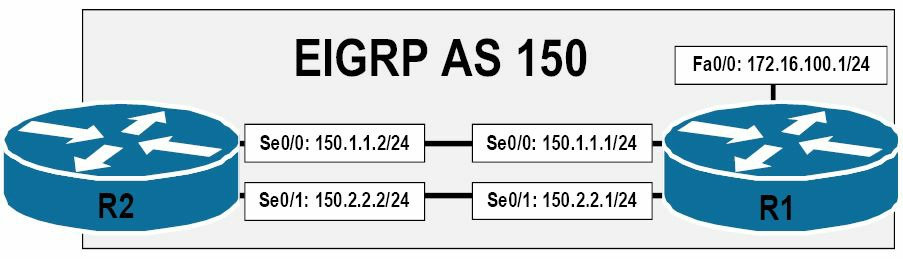 图 36.9 -- EIGRP度量值中延迟的修改
那么从路由器R2到网络172.16.100.0/24的EIGRP度量值的计算如下:
度量值 = [(10^7/路径上的最小带宽) + (延迟综合)] x 256
度量值 = [(10000000/1544) + (2000+10)] x 256
注意: 记住在EIGRP度量值计算中,要将接口延迟数值除以10。
注意: 这里计算出的数值应总是要向下取到最接近的整数。
度量值 = [(10000000/1544) + (2000+10)] x 256
度量值 = [6476 + 2010] x 256
度量值 = 8486 x 256
度量值 = 2172416
可使用show ip route命令对此计算进行验证,如下所示:
R2#show ip route 172.16.100.0 255.255.255.0
Routing entry for 172.16.100.0/24
  Known via “eigrp 150”, distance 90, metric 2172416, type internal
  Redistributing via eigrp 150
  Last update from 150.2.2.1 on Serial0/1, 00:03:28 ago
  Routing Descriptor Blocks:
    150.2.2.1, from 150.2.2.1, 00:03:28 ago, via Serial0/1
      Route metric is 2172416, traffic share count is 1
      Total delay is 20100 microseconds, minimum bandwidth is 1544 Kbit
      Reliability 255/255, minimum MTU 1500 bytes
      Loading 1/255, Hops 1
  * 150.1.1.1, from 150.1.1.1, 00:03:28 ago, via Serial0/0
      Route metric is 2172416, traffic share count is 1
      Total delay is 20100 microseconds, minimum bandwidth is 1544 Kbit
      Reliability 255/255, minimum MTU 1500 bytes
      Loading 1/255, Hops 1
与使用bandwidth命令一样,为了对EIGRP的度量值计算施加影响,我们既可以使用delay命令对接口延迟数值进行提升,也可以对其进行降低。比如,为了将路由器R2配置为使用链路Serial0/0到达172.16.100.0/24网络,而将Serial0/1仅用作一条备份链路,那么就可以如下将Serial0/0上的延迟数值进行降低:
R2(config)#int s0/0
R2(config-if)#delay 100
R2(config-if)#exit
此配置就对经由Serial0/0的路径的EIGRP度量值进行了调整,如下所示:
R2#show ip route 172.16.100.0 255.255.255.0
Routing entry for 172.16.100.0/24
  Known via “eigrp 150”, distance 90, metric 1686016, type internal
  Redistributing via eigrp 150
  Last update from 150.1.1.1 on Serial0/0, 00:01:09 ago
  Routing Descriptor Blocks:
  * 150.1.1.1, from 150.1.1.1, 00:01:09 ago, via Serial0/0
      Route metric is 1686016, traffic share count is 1
      Total delay is 1100 microseconds, minimum bandwidth is 1544 Kbit
      Reliability 255/255, minimum MTU 1500 bytes
      Loading 1/255, Hops 1
而经由Serial0/1的路径,则被保留在拓扑表中,作为到该网络的一条替代路径(an alternate path)。
关于弥散更新算法
The Diffusing Update Algorithm(DUAL)
本小节涉及以下术语:
- 可行距离,the Feasible Distance
- 后继路由器,the Successor
- 报告的距离,the Reported Distance
- 通告的距离, the Advertised Distance, 与报告的距离一样
- 可行后继,the Feasible Successor
- 可行条件,the Feasible Condition
弥散更新算法是EIGRP路由协议的关键所在。弥散更新算法会对从邻居路由器处接收到的所有路由进行观察与比较,然后选出有着到目的网络最低度量值(最优)--该度量值就是可行距离(the Feasible Distance, FD)--的无环回路径,从而得到后续路由(the Successor route)。可行距离既包含了由相连的路由所通告的某网络的度量值,还要加上到那台特定邻居路由器的开销。
由邻居路由器所通告的度量值,就被叫做到目的网路报告的距离(the Reported Distance, RD), 又被叫做到目的网络通告的距离(the Advertised Distance, AD, 所以 RD == AD)。因此,可行距离就包含了报告的距离,加上到达那台特定邻居路由器的开销。那么该后续路由的下一跳路由器,就被叫做是后续路由器(the Successor)。后续路由器就被放入到IP路由表(the IP routing table)及EIGRP拓扑表(the EIGRP topology table)中, 并指向到后继路由器。
到相同目的网络的其它那些有着比起后继路由器路径的可行距离高一些的报告距离,却仍然是无环回的那些路由,就被叫做是可行后继路由器路由了(Any other routes to the same destination network that have a lower RD than the FD of the Successor path are guaranteed to be loop-free and are referred to as Feasible Successor(FS) routes, 这里疑似原作者笔误,“lower”应该是"higher")。这些路由不会被放入到IP路由表中;但它们仍然会与其它后继路由器路由,一起被放入到EIGRP的拓扑表。
为了某条路由成为可行后继路由,则其必须满足可行性条件(the Feasible Condition, FC), 该可行性条件仅会在到目的网络的报告距离少于可行距离时,才会发生。在报告距离高于可行距离时,该路由不会被选作可行后继(FS)。EIGRP这么做是为了防止可能出现的环回。下图36.10中所演示的网络拓扑,将会用于对本小节中出现的术语进行解释。
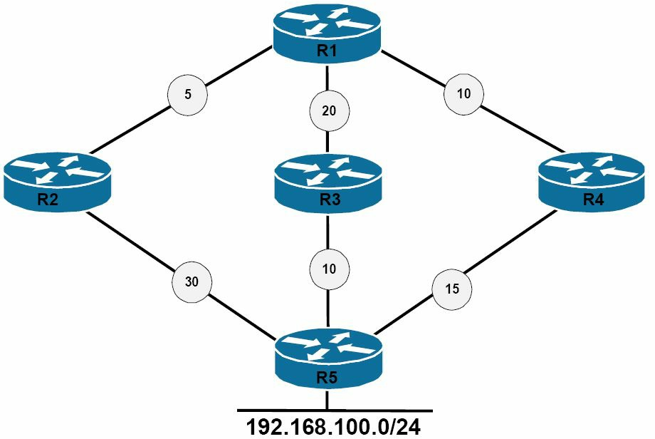 图 36.10 -- 掌握弥散更新算法
参考图36.10, 下表36.4给出了在路由器R1上观察到的到192.168.100.0/24网络的可行距离及报告距离数值:
表 36.4 -- R1的那些路径及距离, R1 Paths and Distances
| 网络路径 | R1 的邻居 |
邻居度量值(报告距离) | R1的可行距离 |
|---|---|---|---|
R1-R2-R5 |
R2 |
30 | 35 |
R1-R3-R5 |
R3 |
10 | 30 |
R1-R4-R5 |
R4 |
15 | 25 |
基于表36.4中的信息,路由器R1将选择经由R4的路径,作为后继路由,这是根据该路由的可行距离得出的。此路由将被放入到IP路由表以及EIGRP拓扑表中。路由器R1随后将对那些到192.168.100.0/24网络的替代路径进行查看。这里邻居路由器R3到192.168.100.0/24网络的度量值,又被叫做是报告的距离或通告距离,就是10。该距离小于(当前的)可行距离,所以该路由满足到可行条件(FC),那么就被放入到EIGRP的拓扑表中。而邻居路由器R2到192.168.100.0/24的度量值为30。该值高于了当前的可行距离25。此路由则不能满足可行条件,就不被看作是一个可行后继(FS)。但该路由仍然会被放入到EIGRP的拓扑表中。这将在后面的EIGRP拓扑表小节,进行演示。
当某个邻居路由器改变了度量值,或拓扑发生了改变,以及后继路由被移除或改变时,弥散更新算法会检查那些可行后继路由器的路由,在发现了一台可行后继路由器时,弥散更新算法就使用该可行后继路由器,以避免不必要的重新计算路由。执行一次本地运算,节省了CPU处理能力,因为在当前后继或主路由失效时,可行后继路由本身就已选出且已经存在了。此过程就叫做本地运算(When a neighbor changes a metric, or when a topology change occurs, and the Successor route is removed or changes, DUAL checks for FSs for the route and if one is found, then DUAL uses it to avoid re-computing the route unnecessarily. This is referred to as local computation. Performing a local computation saves CPU power because the FS has been chosen and already exists before the Successor or primary route fails)。
而当目的网络的可行后继路由器不存在时,本地路由器将向邻居路由器发出一次查询,对邻居路由器是否有着关于目的网络的信息。如邻居路由器有该信息,同时另一路由器确实有着到目的网络的路由,此时该路由器将执行一次弥散运算,以确定出一台新的后继路由器(If the information is available and another neighbour does have a route to the destination network, then the router performs a diffusing computation to determine a new Successor)。
EIGRP的拓扑表
The EIGRP Topology Table
EIGRP的拓扑表,是由EIGRP的各种协议相关模块, 在弥散更新算法的有限状态机之上,运算得到的(The EIGRP topology table is populated by EIGRP PDMs acted upon by the DUAL Finite State Machine)。由已形成邻居关系的EIGRP路由器(neighbouring EIGRP routers)通告的所有目的网络与子网,都被存储在EIGRP拓扑表中。该表包含了后继路由器路由、可行后继路由器路由,甚至那些并不满足可行条件的路由(This includes Successor routes, FS routes, and even routes that have not met the FC)。
正是拓扑表,才令到所有EIGRP路由器对整个网络,有着一致的视图。其还实现了EIGRP网络中的快速收敛。在拓扑表中的每个条目,都包含了某个目的网络及那些通告该目的网络的那些邻居。可行距离及通告距离,都被存储在拓扑表中。EIGRP的拓扑表,包含了构建出一个到所有可达网络的距离与矢量集合的所需信息(The topology table allows all EIGRP routers to have a consistent view of the entire network. It also allows for rapid convergence in EIGRP networks. Each individual entry in the topology table contains the destination network and the neighbour(s) that have advertised the destination network. Both the FD and the RD are stored in the topology table. The EIGRP topology table contains the information needed to build a set of distances and vectors to each reachable network),这些信息包括以下内容:
- 到目的网络的最低带宽, the lowest bandwidth on the path to the destination network
- 到目的网络的总/累积延迟, the total or cumulative delay to the destination network
- 到目的网络路径的可靠性, the reliability of the path to the destination network
- 到目的网络路径的负载,the loading of the path to the destination network
- 到目的网络的最大传输单元的最小值, The minimum Maximum Transmission Unit(MTU) to the destination network
- 到目的网络的可行距离, the Feasible Distance to the destination network
- 由邻居路由器所报告的到目的网络的报告距离, the Reported Distance by the neighbour router to the destination network
- 目的网络的路由源(仅针对那些外部路由),The route source(only external routes) of the destination network
注意: 尽管在拓扑表中包含了最大传输单元(MTU),但EIGRP并不会在实际的度量值计算中使用到该数值。而是该MTU仅简单地作为判断到目的网络数据包大小最小值而被追踪。接口的最大传输单元指定了经某条链路,在无需将数据报或数据包拆分到更小片的情况下,所能传输的数据报最大大小(The interface MTU specifies the largest size of datagram that can be transferred across a certain link without the need of fragmentation, or breaking the datagram or packet into smaller pieces)。
使用show ip eigrp topology命令,就可查看到EIGRP拓扑表的内容。该命令下可用的选项如下所示:
R2#show ip eigrp topology ?
  <1-65535>       AS Number
  A.B.C.D         IP prefix <network>/<length>, e.g., 192.168.0.0/16
  A.B.C.D         Network to display information about
  active          Show only active entries
  all-links       Show all links in topology table
  detail-links    Show all links in topology table
  pending         Show only entries pending transmission
  summary         Show a summary of the topology table
  zero-successors Show only zero successor entries
  |               Output modifiers
  <cr>
不带选项的show ip eigrp topology命令,将仅打印出那些拓扑表中路由的、且是该路由器上所有开启的EIGRP实例的后继路由器及可行后继的信息(The show ip eigrp topology command with no options prints only the Successor and Feasible Successor information for routes in the topology table and for all of the EIGRP instances enabled on the router)。下面演示了该命令的打印输出:
R2#show ip eigrp topology
IP-EIGRP Topology Table for AS(150)/ID(2.2.2.2)
Codes: P - Passive, A - Active, U - Update, Q - Query, R - Reply,
       r - reply Status, s - sia Status
P 150.2.2.0/24, 1 successors, FD is 20512000
        via Connected, Serial0/1
        via 150.1.1.1 (2195456/2169856), Serial0/0
P 150.1.1.0/24, 1 successors, FD is 1683456
        via Connected, Serial0/0
P 172.16.100.0/24, 1 successors, FD is 1686016
        via 150.1.1.1 (1686016/28160), Serial0/0
而show ip eigrp topology [network]/[prefix]及show ip eigrp topology [network] [mask]两个命令,则将打印出其各自所指定路由的后继路由、可行后继路由以及未能满足可行条件的那些其它路由(The show ip eigrp topology [network]/[prefix] and show ip eigrp topology [network] [mask] commands print Successor routes, FS routes, and routes that have not met the FC for the route specified in either command)。下面的输出演示了show ip eigrp topology [network]/[prefix]命令的用法:
R2#show ip eigrp topology 172.16.100.0/24
IP-EIGRP (AS 150): Topology entry for 172.16.100.0/24
  State is Passive, Query origin flag is 1, 1 Successor(s), FD is 1686016
  Routing Descriptor Blocks:
  150.1.1.1 (Serial0/0), from 150.1.1.1, Send flag is 0x0
      Composite metric is (1686016/28160), Route is Internal
      Vector metric:
        Minimum bandwidth is 1544 Kbit
        Total delay is 1100 microseconds
        Reliability is 255/255
        Load is 1/255
        Minimum MTU is 1500
        Hop count is 1
  150.2.2.1 (Serial0/1), from 150.2.2.1, Send flag is 0x0
      Composite metric is (2167998207/2147511807), Route is Internal
      Vector metric:
        Minimum bandwidth is 128 Kbit
        Total delay is 83906179 microseconds
        Reliability is 255/255
        Load is 1/255
        Minimum MTU is 1500
        Hop count is 1
在上面的输出中,可以看出经由Serial0/1的路径并没有满足可行条件(FC),因为其报告的距离(RD)超过了可行距离(FD)。这就是该路径没有在show ip eigrp topology命令的输出中打印出来的原因。而为了判断出那些后继路由、可行后继路由,以及未能满足可行条件的那些路由,就可以使用show ip eigrp topology all-links命令,而不是对单个前缀进行查看,从而查看到在EIGRP拓扑表中所有前缀的所有可能的路由。下面对此命令的输出进行了演示:
R2#show ip eigrp topology all-links
IP-EIGRP Topology Table for AS(150)/ID(2.2.2.2)
Codes: P - Passive, A - Active, U - Update, Q - Query, R - Reply,
       r - reply Status, s - sia Status
P 150.2.2.0/24, 1 successors, FD is 20512000, serno 42
        via Connected, Serial0/1
        via 150.1.1.1 (2195456/2169856), Serial0/0
P 150.1.1.0/24, 1 successors, FD is 1683456, serno 32
        via Connected, Serial0/0
        via 150.2.2.1 (21024000/2169856), Serial0/1
P 172.16.100.0/24, 1 successors, FD is 1686016, serno 47
        via 150.1.1.1 (1686016/28160), Serial0/0
        via 150.2.2.1 (2167998207/2147511807), Serial0/1
在该EIGRP拓扑表中的路由条目,可能被标记为被动的(Passive, P)或主动的(Active, A)状态。处于被动状态的某条路由,表明EIGRP已经完成了该路由度量值的主动计算,同时可以使用该后继路由将流量转发到目的网络。此状态是拓扑表中所有路由的首选状态。
当后继路由丢失,且路由器为确定出可行后继而发出了一个查询数据包时,那些EIGRP的路由就处于主动状态了。通常情况下,是存在着可行后继的,且EIGRP会将那个可行后继提升为后继路由。那么在此情况下,就无需涉及到网络中其它路由器,该路由器就可以完成收敛。此过程就叫做一次本地运算(Enhanced IGRP routes are in Active state when the Successor route has been lost and the router sends out a Query packet to determine an FS. Usually, an FS is present and EIGRP promotes that to the Successor route. This way, the router converges without involving other routers in the network. This process is referred to as a local computation)。
不过,如后继路由已丢失或被移除,而又没有可行后继时,那么路由器就将开始弥散运算(diffused computation)。在弥散运算中,EIGRP将往所有邻居路由器、从除开连接到后继路由的接口外的所有接口发出一次查询。当某台EIGRP邻居路由器收到某条路由的查询时,如那个邻居的EIGRP拓扑表中没有包含该被查询路由的条目,那么这个邻居就立即对该查询应答一条不可达报文,指出经过此邻居处并无这条路由的路径。
而如果邻居路由器上的EIGRP拓扑表已将发出查询的路由器,列为所查询路由的后继路由器,同时存在一条可行后继路由,那么该可行后继路由器路由就被安装起来,同时该邻居路由器对该邻居查询做出其有着一条到已丢失目的网络路由的应答(If the EIGRP topology table on the neighbour lists the router sending the Query as the Successor for that route, and an FS exists, then the FS is installed and the router replies to the neighbour Query that it has a route to the lost destination network)。
但如果该EIGRP拓扑表虽然将发出查询的路由器列为了该路由的后继路由器,却没有可行后继时,收到查询的路由器就会查询其所有的EIGRP邻居,除开那些作为其先前后继路由器而发出的同样接口。在尚未收到对此路由的所有查询的一条应答时,该路由器不会对先前的查询进行响应(However, if the EIGRP topology table lists the router sending the Query as the Successor for this route and there is no FS, then the router queries all of its EIGRP neighbors, except those that were sent out of the same interface as its former Successor. The router will not reply to the Query until it has received a Reply to all Queries that it originated for this route)。
最后,如某个非此目的网络后继的邻居收到了此次查询,随后该路由器以其自己的后继信息予以了应答。而假如这些邻居路由器仍然没有该已丢失的路由信息,那么这些邻居路由器就会向它们自己的邻居路由器发出查询,直到抵达查询边界。所谓查询边界,既可以是网络的末端、分发清单的边界,或者汇总的边界(Finally, if the Query was received from a neighbour that is not the Successor for this destination, then the router replies with its own Successor information. If the neighbouring routers do not have the lost route information, then Queries are sent from those neighbouring routers to their neighbouring routers until the Query boundary is reached. The Query boundary is either the end of the network, the distribute list boundary, or the summarization boundary)。
查询一旦发出,那么发出查询的EIGRP路由器就必须在计算后继路由前,等待完成所有应答的接收。如有任何邻居在三分钟之内没有应答,那么该路由就被称作处于活动粘滞状态(If any neighbour has not replied within three minutes, the route is said to be Stuck-In-Active(SIA))。而当某条路由成为活动粘滞路由时,该(这些)未对查询进行响应的路由器的邻居关系,就将被重置。在此情况下,可以观察到路由器记录下了如下类似的一条消息:
%DUAL-5-NBRCHANGE: IP-EIGRP 150:
    Neighbor 150.1.1.1(Serial0/0) is down: stuck in active
%DUAL-3-SIA:
    Route 172.16.100.0/24 stuck-in-active state in IP-EIGRP 150.
Cleaning up
造成(这些)EIGRP邻居路由器未能对查询进行响应的原因有几种,包括下面这些:
- 该邻居路由器的CPU过载了,因此而无法及时响应
- 该邻居路由器本身就没有关于那条丢失路由的信息
- 电路质量问题,造成数据包丢失
- 某些低带宽链路拥塞,从而造成数据包的延迟
而为了防止因为延迟响应造成的来自其它EIGRP邻居的活动粘滞方面的故障,可使用路由器配置模式中的timers active-time命令,将本地路由器配置为等待多于默认的三分钟,以接收到返回给其查询数据包的响应。
注意: 重要的是应注意在对网络中某台路由器上的该默认参数进行修改时,就必须对EIGRP路由域中的所有路由器上的该参数进行修改(It is important to note that if you change this default parameter on one EIGRP router in your network, you must change it on all the other routers within your EIGRP routing domain)。
相等开销及不相等开销下的负载均衡
Equal Cost and Unequal Cost Load Sharing
思科IOS软件对所有路由协议支持默认下至多4条路径的相等开销负载均衡(Cisco IOS software supports equal cost load sharing for a default of up to four paths for all routing protocols)。下面的show ip protocols命令的输出,对此进行了演示:
R2#show ip protocols
Routing Protocol is “eigrp 150”
  Outgoing update filter list for all interfaces is not set
  Incoming update filter list for all interfaces is not set
  Default networks flagged in outgoing updates
  Default networks accepted from incoming updates
  EIGRP metric weight K1=1, K2=0, K3=1, K4=0, K5=0
  EIGRP maximum hopcount 100
  EIGRP maximum metric variance 1
  Redistributing: eigrp 150
  EIGRP NSF-aware route hold timer is 240s
  Automatic network summarization is not in effect
  Maximum path: 4
  Routing for Networks:
    150.1.1.2/32
    150.2.2.2/32
  Routing Information Sources:
    Gateway         Distance      Last Update
    Gateway         Distance      Last Update
    150.2.2.1       90            00:00:52
    150.1.1.1       90            00:00:52
  Distance: internal 90 external 170
而又可以使用路由器配置命令maximum-paths <1-6>,对默认的最多4条路径,修改为最多6条相等开销的路径。在进行相等开销的负载均衡时,路由器将负载在所有路径直接进行均匀地分配。有着一个流量分享计数,对每条路径上传输的数据包进行识别(The traffic share count identifies the number of outgoing packets on each path)。在进行相等开销的负载均衡时,单个的完整数据包是在某条单独路径上发出的,如下面的输出所示:
R2#show ip route 172.16.100.0 255.255.255.0
Routing entry for 172.16.100.0/24
  Known via “eigrp 150”, distance 90, metric 2172416, type internal
  Redistributing via eigrp 150
  Last update from 150.2.2.1 on Serial0/1, 00:04:00 ago
  Routing Descriptor Blocks:
    150.2.2.1, from 150.2.2.1, 00:04:00 ago, via Serial0/1
      Route metric is 2172416, traffic share count is 1
      Total delay is 20100 microseconds, minimum bandwidth is 1544 Kbit
      Reliability 255/255, minimum MTU 1500 bytes
      Loading 1/255, Hops 1
  * 150.1.1.1, from 150.1.1.1, 00:04:00 ago, via Serial0/0
      Route metric is 2172416, traffic share count is 1
      Total delay is 20100 microseconds, minimum bandwidth is 1544 Kbit
      Reliability 255/255, minimum MTU 1500 bytes
      Loading 1/255, Hops 1
除了相等开销下的负载均衡能力,EIGRP还能完成不相等开销下的负载均衡。这种特别的能力令到EIGRP能够使用那些不相等开销的路径,基于不同的流量分享权重数值,从而将传输中的数据包发送到目的网络(This unique ability allows EIGRP to use unequal cost paths to send outgoing packets to the destination network based on weighted traffic share values)。通过使用路由器配置命令variance <multiplier>,就可以开启不相等开销下的负载均衡特性。
关键字<multiplier>是一个介于1到128之间的整数。默认的倍数(multiplier)1,就是说不进行不相等开销下的负载均衡。此默认设置在下面的show ip protocols命令的输出中进行了演示:
R2#show ip protocols
Routing Protocol is “eigrp 150”
  Outgoing update filter list for all interfaces is not set
  Incoming update filter list for all interfaces is not set
  Default networks flagged in outgoing updates
  Default networks accepted from incoming updates
  EIGRP metric weight K1=1, K2=0, K3=1, K4=0, K5=0
  EIGRP maximum hopcount 100
  EIGRP maximum metric variance 1
  Redistributing: eigrp 150
  EIGRP NSF-aware route hold timer is 240s
  Automatic network summarization is not in effect
  Maximum path: 4
  Routing for Networks:
    150.1.1.2/32
    150.2.2.2/32
  Routing Information Sources:
    Gateway         Distance      Last Update
    150.2.2.1             90      00:00:52
    150.1.1.1             90      00:00:52
  Distance: internal 90 external 170
该倍数是一个可变的整数, 告诉路由器在那些有着低于最小度量值乘以该倍数的那些路由上,进行负载均衡(The multiplier is a variable integer that tells the router to load share across routes that have a metric that is less than the minimum metric multiplied by the multiplier)。比如,在指定了5的变化时(specifying a variance of 5),就指示路由器在那些度量值低于最小度量值5倍的路由上,进行负载均衡。在使用了variance命令,同时指定了除开1之外的倍数时,该路由器就将在这些满足条件的路由上,按照各条路由的度量值,成比例的分配流量。也就是说,对于那些有着较低度量值的路由,比起那些有着较高度量值的路由,要经由其发送更多的流量。
下图36.11演示了一个基本的运行EIGRP的网络。其中的路由器R1和R2,是通过背靠背的串行链路连接起来的(R1 and R2 are connected via back-to-back Serial links)。两台路由器间的链路150.1.1.0/24,有着1024Kbps的带宽。两台路由器之间的150.2.2.0/24链路,有着768Kpbs的带宽。路由器R1是通过EIGRP将172.16.100.0/24前缀,通告给R2的。
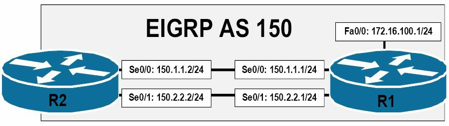 图 36.11 -- 掌握EIGRP的非等价负载均衡,Understanding EIGRP Variance
基于图36.11中所演示的拓扑,下面的输出演示在路由器R2上172.16.100.0/24前缀的路由表:
R2#show ip route 172.16.100.0 255.255.255.0
Routing entry for 172.16.100.0/24
  Known via “eigrp 150”, distance 90, metric 3014400, type internal
  Redistributing via eigrp 150
  Last update from 150.1.1.1 on Serial0/0, 00:00:11 ago
  Routing Descriptor Blocks:
  * 150.1.1.1, from 150.1.1.1, 00:00:11 ago, via Serial0/0
      Route metric is 3014400, traffic share count is 1
      Total delay is 20100 microseconds, minimum bandwidth is 1024 Kbit
      Reliability 255/255, minimum MTU 1500 bytes
      Loading 1/255, Hops 1
下面的EIGRP拓扑表,同时显示了后继与可行后继路由:
R2#show ip eigrp topology 172.16.100.0 255.255.255.0
IP-EIGRP (AS 150): Topology entry for 172.16.100.0/24
  State is Passive, Query origin flag is 1, 1 Successor(s), FD is 3014400
  Routing Descriptor Blocks:
  150.1.1.1 (Serial0/0), from 150.1.1.1, Send flag is 0x0
      Composite metric is (3014400/28160), Route is Internal
      Vector metric:
        Minimum bandwidth is 1024 Kbit
        Total delay is 20100 microseconds
        Reliability is 255/255
        Load is 1/255
        Minimum MTU is 1500
        Hop count is 1
  150.2.2.1 (Serial0/1), from 150.2.2.1, Send flag is 0x0
      Composite metric is (3847680/28160), Route is Internal
      Vector metric:
        Minimum bandwidth is 768 Kbit
        Total delay is 20100 microseconds
        Reliability is 255/255
        Load is 1/255
        Minimum MTU is 1500
        Hop count is 1
这里为了确定要配置到路由器上的非等价负载均衡数值(the variance value to configure on the router), 就可使用下面的公式:
非等价负载均衡数值(Variance) = 考虑要用到路径的度量值中最高的/最优路径的度量值(最小的度量值)
使用此公式,就可以像下面这样,计算出在路由器R2上,所要配置的非等价负载均衡数值:
非等价负载均衡数值(Variance) = 考虑要用到路径的度量值中最高的/最优路径的度量值(最小的度量值)
非等价负载均衡数值(Variance) = 3847680/3014400
非等价负载均衡数值(Variance) = 1.28
随后必须对此数值进行向上取整,这里就是2了。那么就可以在路由器配置模式中,通过应用将下面的配置,将路由器R2配置为进行非等价的负载均衡了:
R2(config)#router eigrp 150
R2(config-router)#variance 2
R2(config-router)#exit
而根据此配置,此时172.16.100.0/24前缀的路由表条目就变成如下所示了:
R2#show ip route 172.16.100.0 255.255.255.0
Routing entry for 172.16.100.0/24
  Known via “eigrp 150”, distance 90, metric 3014400, type internal
  Redistributing via eigrp 150
  Last update from 150.2.2.1 on Serial0/1, 00:00:36 ago
  Routing Descriptor Blocks:
    150.2.2.1, from 150.2.2.1, 00:00:36 ago, via Serial0/1
      Route metric is 3847680, traffic share count is 47
      Total delay is 20100 microseconds, minimum bandwidth is 768 Kbit
      Reliability 255/255, minimum MTU 1500 bytes
      Loading 1/255, Hops 1
  * 150.1.1.1, from 150.1.1.1, 00:00:36 ago, via Serial0/0
      Route metric is 3014400, traffic share count is 60
      Total delay is 20100 microseconds, minimum bandwidth is 1024 Kbit
      Reliability 255/255, minimum MTU 1500 bytes
      Loading 1/255, Hops 1
其中的流量分配计数(The traffic share count)表明,每从Serial0/0转发60个数据包,路由器就将从Serial0/1转发47个数据包。数据包的转发,是依两条路径的路由度量值的比例完成的。这是在应用了variance命令后的默认行为。而通过路由器配置命令traffic-share balanced(the traffic-share balanced router configuration command),就可以开启此智能流量分配功能(this intelligent traffic sharing functionality),该命令无需显式配置(默认是开启的)。
注意: 该
traffic-share balanced命令默认是开启的,且就算对其进行了显式配置,其也不会在运行配置中出现。这一点在下面进行了演示:
R2(config)#router eigrp 150
R2(config-router)#vari 2
R2(config-router)#traffic-share balanced
R2(config-router)#exit
R2(config)#do show run | begin router
router eigrp 150
variance 2
network 150.1.1.2 0.0.0.0
network 150.2.2.2 0.0.0.0
no auto-summary
如同本小节前面指出的那样,在使用了variance命令时,所有那些满足了可行条件、且有着低于最小度量值乘以那个倍数的路径,都将被安装到路由表中。路由器随后将使用到所有路径,并依据其各自的路由度量值来按比例地进行负载均衡。
在某些情况下,可能打算将那些替代路由,比如可行后继路,预先放入到路由表中,却只在后继路由被移除时,才使用它们。执行这类操作的典型目的,是为在开启EIGRP的网络中降低收敛时间。要弄明白此概念,就要回忆一下,路由器默认是只将后继路由放入到路由表中的。而在后继路由已不可用时,可行后继路由就被提升为后继路由。随后该路由才被装入到路由表中,作为到目的网络的主要路径。
可将路由器配置命令traffic-share min across-interfaces,与variance命令结合使用,从而将那些有着少于最小度量值乘以所指定倍数所有路由,都安装到路由表中,却仅使用最小(最优)度量值的那条路由(后继路由),来转发数据包,直到该路由变为不可用。此配置的主要目的,就是在主路由丢失时,保证替代路由已经处于路由表中,且立即可用(从而达到减少收敛时间的目的)。
下面的配置示例,使用了以上图36.11中展示的拓扑,用于对如何将路由器配置为把那些度量值少于最小度量值两倍的路由,放入到路由表中,而仅使用有着最低度量值的那条路由(后继路由)来转发数据包:
R2(config)#router eigrp 150
R2(config-router)#vari 2
R2(config-router)#traffic-share min across-interfaces
R2(config-router)#exit
此配置造成路由表中172.16.100.0/24前缀的以下输出:
R2#show ip route 172.16.100.0 255.255.255.0
Routing entry for 172.16.100.0/24
  Known via “eigrp 150”, distance 90, metric 3014400, type internal
  Redistributing via eigrp 150
  Last update from 150.2.2.1 on Serial0/1, 00:09:01 ago
  Routing Descriptor Blocks:
    150.2.2.1, from 150.2.2.1, 00:09:01 ago, via Serial0/1
      Route metric is 3847680, traffic share count is 0
      Total delay is 20100 microseconds, minimum bandwidth is 768 Kbit
      Reliability 255/255, minimum MTU 1500 bytes
      Loading 1/255, Hops 1
  * 150.1.1.1, from 150.1.1.1, 00:09:01 ago, via Serial0/0
      Route metric is 3014400, traffic share count is 1
      Total delay is 20100 microseconds, minimum bandwidth is 1024 Kbit
      Reliability 255/255, minimum MTU 1500 bytes
      Loading 1/255, Hops 1
如上面的输出所示,基于该种不同开销下的负载均衡配置,两条不同度量值的路由,已被安装到路由表中。但注意到经由Serial0/1的流量分享计数(the traffic share count)是0,而经由Serial0/0的计数为1。这就意味着,尽管该路由条目已被安装到路由表中, 该路由器不会通过Serial0/1,向172.16.100.0/24网络发送任何数据包,除非经由Serial0/0的路径不再可用。
使用EIGRP作默认路由
Default Routing Using EIGRP
在将最终网关或网络动态地通告给路由域中的其它路由器方面,EIGRP支持多种不同方式。最终网关,或默认路由,是在目的网络未在路由表中特别列出时,路由器用于引导流量的一种方式(Enhanced IGRP supports numerous ways to advertise dynamically the gateway or network of last resort to other routers within the routing domain. A gateway of last resort, or default route, is a method for the router to direct traffic when the destination network is not specifically listed in the routing table)。而在此种情形下,路由器引导流量的方式有:
- 使用
ip default-network命令, using theip default-networkcommand - 使用
network命令来对网络0.0.0.0/0通告, using thenetworkcommand to advertise network0.0.0.0/0 - 对默认静态路由进行重分发, Redistributing the default static route
- 使用命令
ip summary-address eigrp [asn] [network] [mask], using theip summary-address eigrp [asn] [network] [mask]command
而第一种,使用ip default-network命令,被认为是一种EIGRP下对默认路由进行动态通告的过时方式。但因为在当前的IOS软件中仍然支持这种方式,所以这里有必要提到。
ip default-network配置命令通过把一个星号,插入到路由表中某个网络旁边,而将该网络标记为默认网络。那些目的地没有明确路由表条目的流量,就会被路由器转发到这个网络(Traffic for destinations to which there is no specific routing table entry is then forwarded by the router to this network)。下面参考图36.12中的EIGRP拓扑,对此种部署进行了演示:
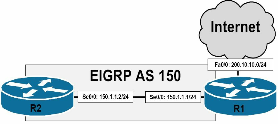 图 36.12 -- EIGRP的默认路由
参考图36.12, 假设子网200.10.10.0/24是连接到互联网的。该子网位于路由器R1的Fastethernet0/0侧。路由器R1与R2相应地通过一条背靠背的串行连接相连。两台路由器都是处于EIGRP AS 150中。为了将200.10.10.0/24标记为最终网络,就要在路由器R1上进行如下配置:
R1(config)#router eigrp 150
R1(config-router)#network 200.10.10.0 0.0.0.255
R1(config-router)#exit
R1(config)#ip default-network 200.10.10.0
R1(config)#exit
基于此配置,路由器R2就会将200.10.10.0/24作为最终网络接收下来,如下所示:
R2#show ip route
Codes: C - connected, S - static, R - RIP, M - mobile, B - BGP
       D - EIGRP, EX - EIGRP external, O - OSPF, IA - OSPF inter area
       N1 - OSPF NSSA external type 1, N2 - OSPF NSSA external type 2
       E1 - OSPF external type 1, E2 - OSPF external type 2
       i - IS-IS, su - IS-IS summary, L1 - IS-IS level-1, L2 - IS-IS level-2
       ia - IS-IS inter area, * - candidate default, U - per-user static route
       o - ODR, P - periodic downloaded static route
Gateway of last resort is 150.2.2.1 to network 200.10.10.0
D*   200.10.10.0/24 [90/2172416] via 150.2.2.1, 00:01:03, Serial0/0
     150.1.0.0/24 is subnetted, 1 subnets
C       150.1.1.0 is directly connected, Serial0/0
network命令可用于对某条既有的指向某个物理或逻辑接口,通常是Null0接口的静态默认路由,进行通告(The network command can be used to advertise an existing static default route point to either a physical or a logical interface, typically the Null0 interface)。
注意:
Null0接口是路由器上的一个虚拟接口,会将路由至该接口的所有流量进行抛弃处理。如有着一条指向Null0的静态路由,那么所有以该静态路由中所指定网络为目的的流量,都将被简单地做丢弃处理。可将Null0接口看着是一个黑洞:数据包进入了,但不会有任何东西离开那里。其基本上就是路由器上的一个数位垃圾桶(It is essentially a bit-bucket on the router)。
参考上面的图36.12, network命令与一条既有默认静态路由的结合使用,在以下路由器R1的配置中进行了演示:
R1(config)#ip route 0.0.0.0 0.0.0.0 FastEthernet0/0
R1(config)#router eigrp 150
R1(config-router)#network 0.0.0.0
R1(config-router)#exit
基于此种配置,下面的输出,演示了路由器R2上的IP路由表:
R2#show ip route
Codes: C - connected, S - static, R - RIP, M - mobile, B - BGP
       D - EIGRP, EX - EIGRP external, O - OSPF, IA - OSPF inter area
       N1 - OSPF NSSA external type 1, N2 - OSPF NSSA external type 2
       E1 - OSPF external type 1, E2 - OSPF external type 2
       i - IS-IS, su - IS-IS summary, L1 - IS-IS level-1, L2 - IS-IS level-2
       ia - IS-IS inter area, * - candidate default, U - per-user static route
       o - ODR, P - periodic downloaded static route
Gateway of last resort is 150.1.1.1 to network 0.0.0.0
D    200.10.10.0/24 [90/2172416] via 150.1.1.1, 00:01:11, Serial0/0
     150.1.0.0/24 is subnetted, 1 subnets
C       150.1.1.0 is directly connected, Serial0/0
D*   0.0.0.0/0 [90/2172416] via 150.1.1.1, 00:00:43, Serial0/0
尽管路由重分发(route redistribution)不是CCNA考试部分,这里仍将对其进行一个概述。路由重分发正是通过EIGRP对一条默认路由进行通告的第三种方式。为将现有的静态默认路由重分发到EIGRP中,就要使用路由器配置命令redistribute static metric [bandwidth] [delay] [reliability] [load] [MTU]。用于本小节中前面那些输出的同一网络拓扑,将用于对这种方式的部署进行演示,如下图36.13所示:
 图 36.13 -- EIGRP的默认路由(续)
参考图36.13, 该图与图36.12是一样的,在路由器R1上完成以下配置:
R1(config)#ip route 0.0.0.0 0.0.0.0 FastEthernet0/0
R1(config)#router eigrp 150
R1(config-router)#redistribute static metric 100000 100 255 1 1500
R1(config-router)#exit
注意: 这里度量值中所用到的那些数值,可从接口上进行继承到,或可以在使用此命令时指定想要的任意数值。
基于此种配置,路由器R2上的路由表就如下所示了:
R2#show ip route
Codes: C - connected, S - static, R - RIP, M - mobile, B - BGP
       D - EIGRP, EX - EIGRP external, O - OSPF, IA - OSPF inter area
       N1 - OSPF NSSA external type 1, N2 - OSPF NSSA external type 2
       E1 - OSPF external type 1, E2 - OSPF external type 2
       i - IS-IS, su - IS-IS summary, L1 - IS-IS level-1, L2 - IS-IS level-2
       ia - IS-IS inter area, * - candidate default, U - per-user static route
       o - ODR, P - periodic downloaded static route
Gateway of last resort is 150.1.1.1 to network 0.0.0.0
     150.1.0.0/24 is subnetted, 1 subnets
C       150.1.1.0 is directly connected, Serial0/0
D*EX 0.0.0.0/0 [170/2195456] via 150.1.1.1, 00:01:16, Serial0/0
因为该路由是在路由器R1上被重分发到EIGRP中的,所以如同上面所反应出的,其就是一条外部EIGRP路由了。对于那些外部路由,EIGRP拓扑表中就包含了诸如该路由所起源的路由器、该路由是为何种协议接收的,以及该外部路由的度量值等信息。下面的输出对此进行了演示:
R2#show ip eigrp topology 0.0.0.0/0
IP-EIGRP (AS 150): Topology entry for 0.0.0.0/0
  State is Passive, Query origin flag is 1, 1 Successor(s), FD is 2195456
  Routing Descriptor Blocks:
  150.1.1.1 (Serial0/0), from 150.1.1.1, Send flag is 0x0
      Composite metric is (2195456/51200), Route is External
      Vector metric:
        Minimum bandwidth is 1544 Kbit
        Total delay is 21000 microseconds
        Reliability is 255/255
        Load is 1/255
        Minimum MTU is 1500
        Hop count is 1
      External data:
        Originating router is 1.1.1.1
        AS number of route is 0
        External protocol is Static, external metric is 0
        Administrator tag is 0 (0x00000000)
        Exterior flag is set
可以看出该默认路由是一条在路由器R1上重分发到EIGRP中的静态路由。该路由有着度量值0。此外还可以看出路由器R1的EIGRP路由器ID(the EIGRP router ID, RID)为1.1.1.1。
对默认路由进行通告的最后一种方法,就是使用接口配置命令ip summary-address eigrp [asn] [network] [mask]了。在本课程模块的后面,将对EIGRP的路由汇总(EIGRP route summarization)进行详细讲解。这里要着重于在应用EIGRP时,使用此命令来对默认路由进行通告的用途。
参考上面图36.13中所演示的网络拓扑图示,这里使用了接口配置命令ip summary-address eigrp [asn] [network] [mask], 将路由器R1配置为把默认路由通告给R2,如下所示:
R1(config)#interface Serial0/0
R1(config-if)#description ‘Back-to-Back Serial Connection To R2 Serial0/0’
R1(config-if)#ip summary-address eigrp 150 0.0.0.0 0.0.0.0
R1(config-if)#exit
使用这个命令的主要优势在于,无需为了让EIGRP将网络0.0.0.0/0通告给邻居路由器,而将某条默认路由或某个默认网络放入到路由表中(The primary advantage to using this command is that a default route or network does not need to exist in the routing table in order for EIGRP to advertise network 0.0.0.0/0 to its neighbour routers)。在执行了此命令后,本地路由器将生成一条到Null0接口的汇总路由,并将该条目标记为备选默认路由(the candidate default route)。如下所示:
R1#show ip route
Codes: C - connected, S - static, R - RIP, M - mobile, B - BGP
       D - EIGRP, EX - EIGRP external, O - OSPF, IA - OSPF inter area
       N1 - OSPF NSSA external type 1, N2 - OSPF NSSA external type 2
       E1 - OSPF external type 1, E2 - OSPF external type 2
       i - IS-IS, su - IS-IS summary, L1 - IS-IS level-1, L2 - IS-IS level-2
       ia - IS-IS inter area, * - candidate default, U - per-user static route
       o - ODR, P - periodic downloaded static route
Gateway of last resort is 0.0.0.0 to network 0.0.0.0
     150.1.0.0/24 is subnetted, 1 subnets
C       150.1.1.0 is directly connected, Serial0/0
D*   0.0.0.0/0 is a summary, 00:02:26, Null0
于是在路由器R2上就作为一条内部EIGRP路由(an internal EIGRP route),接收到该汇总路由,如下所示:
R2#show ip route
Codes: C - connected, S - static, R - RIP, M - mobile, B - BGP
       D - EIGRP, EX - EIGRP external, O - OSPF, IA - OSPF inter area
       N1 - OSPF NSSA external type 1, N2 - OSPF NSSA external type 2
       E1 - OSPF external type 1, E2 - OSPF external type 2
       i - IS-IS, su - IS-IS summary, L1 - IS-IS level-1, L2 - IS-IS level-2
       ia - IS-IS inter area, * - candidate default, U - per-user static route
       o - ODR, P - periodic downloaded static route
Gateway of last resort is 150.1.1.1 to network 0.0.0.0
     150.1.0.0/24 is subnetted, 1 subnets
C       150.1.1.0 is directly connected, Serial0/0
D*   0.0.0.0/0 [90/2297856] via 150.1.1.1, 00:03:07, Serial0/0
EIGRP网络中的水平分割
Split Horizon in EIGRP Networks
前面已获悉水平分割是一项距离矢量协议的特性,该特性强制路由信息无法从接收到的接口再发送回去,这样做就阻止了路由信息重新通告到学习到其的同一接口(Previously, you learned that split horizon is a Distance Vector protocol feature mandating that routing information cannot be sent back out of the same interface through which it was received. This prevents the re-advertising of information back to the source from which it was learned)。虽然这个特征是一种很好的环回防止机制(a great loop prevention mechanism),但其也是一项明显的缺陷,特别是在星形网络中(especially in hub-and-spoke networks)。为更好地理解此特性的不足,就要参考下面图36.14中的EIGRP星形网络:
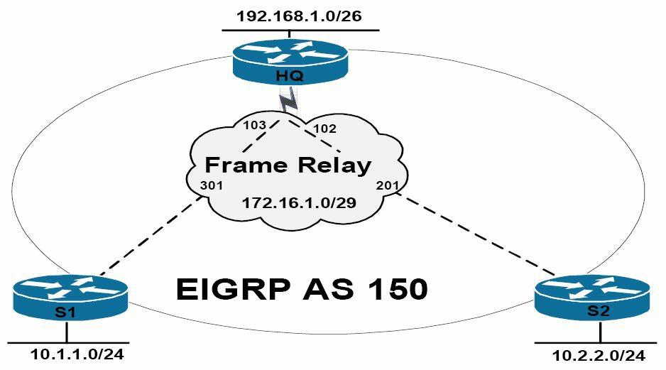 图 36.14 -- EIGRP的水平分割
图36.14中的拓扑,演示了一个典型的星形网络,其中的总部路由器(router HQ)是中心路由器(the hub router), 路由器S1与S2则是分支路由器(the spoke router)。在该帧中继广域网上,每台分支路由器都有着一个在部分网状拓扑(a partial-mesh topology)中,各自与中心路由器之间的,所提供的数据链路层连接标识(Data Link Connection Identifier,这是个6位标识,表示正在进行的客户和服务器之间的连接。用于RFCOMM 层。On the Frame Relay WAN, each spoke router has a single DLCI provisioned between itself and the HQ router in a partial-mesh topology)。下面对这些路由器上的帧中继配置进行了检查:
HQ#show frame-relay map
Serial0/0 (up): ip 172.16.1.2 dlci 102(0x66,0x1860), static,
              broadcast,
              CISCO, status defined, active
Serial0/0 (up): ip 172.16.1.1 dlci 103(0x67,0x1870), static,
              broadcast,
              CISCO, status defined, active

S1#show frame-relay map
Serial0/0 (up): ip 172.16.1.2 dlci 301(0x12D,0x48D0), static,
              broadcast,
              CISCO, status defined, active
Serial0/0 (up): ip 172.16.1.3 dlci 301(0x12D,0x48D0), static,
              broadcast,
              CISCO, status defined, active

S2#show frame-relay map
Serial0/0 (up): ip 172.16.1.1 dlci 201(0xC9,0x3090), static,
              broadcast,
              CISCO, status defined, active
Serial0/0 (up): ip 172.16.1.3 dlci 201(0xC9,0x3090), static,
              broadcast,
              CISCO, status defined, active
在后面的广域网章节,将涉及到帧中继。这里在所有三台路由器上都开启了EIGRP,使用了自治系统编号150。下面的输出演示了中心路由器与分支路由器之间的EIGRP邻居关系:
HQ#show ip eigrp neighbors
IP-EIGRP neighbors for process 150
H   Address        Interface     Hold  Uptime    SRTT  RTO   Q   Seq
                                (sec)            (ms)        Cnt Num
1   172.16.1.1     Se0/0        165    00:01:07  24    200   0   2
0   172.16.1.2     Se0/0        153    00:01:25  124   744   0   2
下面的输出对第一台分支路由器S1与中心路由器之间的EIGRP邻居关系:
S1#show ip eigrp neighbors
IP-EIGRP neighbors for process 150
H   Address        Interface     Hold  Uptime    SRTT  RTO   Q   Seq
                                (sec)            (ms)        Cnt Num
0   172.16.1.3     Se0/0        128    00:00:53  911   5000  0   4
下面的输出对第二台分支路由器S2与中心路由器之间的EIGRP邻居关系:
S2#show ip eigrp neighbors
IP-EIGRP neighbors for process 150
H   Address        Interface     Hold  Uptime    SRTT  RTO   Q   Seq
                                (sec)            (ms)        Cnt Num
0   172.16.1.3     Se0/0        156    00:02:20  8     200   0   4
默认EIGRP的水平分割是开启的,但在局部网状网络的非广播多路访问网络上,EIGRP的水平分割是不合需要的(By default, EIGRP split horizon is enabled, which is undesirable in partial-mesh NBMA networks)。这就意味着对于那些在Serial0/0上学习到的路由信息,中心路由器不会再从相同接口(Serial0/0)进行通告。而这种默认行为的效果,就是中心路由器不会将接收自路由器S1的10.1.1.0/24前缀,通告给S2,因为该路由是经由Serial0/0接口接收到的,而水平分割特性阻止了该路由器对从该接口学习到的信息,在通告出同一接口。这一点对于中心路由器接收自路由器S2的10.2.2.0/24前缀同样适用。
这种默认行为意味着尽管中心路由器注意到了这两条前缀,但分支路由器却只有局部的路由表。中心路由器上的路由表如下:
HQ#show ip route eigrp
     10.0.0.0/8 is variably subnetted, 2 subnets, 2 masks
D       10.1.1.0/24 [90/2195456] via 172.16.1.1, 00:12:04, Serial0/0
D       10.2.2.0/24 [90/2195456] via 172.16.1.2, 00:12:06, Serial0/0
分支路由器S1上的路由表如下:
S1#show ip route eigrp
     192.168.1.0/26 is subnetted, 1 subnets
D       192.168.1.0 [90/2195456] via 172.16.1.3, 00:10:53, Serial0/0
分支路由器S2上的路由表如下:
S2#show ip route eigrp
     192.168.1.0/26 is subnetted, 1 subnets
D       192.168.1.0 [90/2195456] via 172.16.1.3, 00:10:55, Serial0/0
这种默认行为的结果,就是尽管中心(总部)路由器能够到达两个分支路由器的网络,但两台分支路由器却都无法到达对方的网络。解决此种情况的方法有几种,如下所示:
- 在中心路由器上关闭水平分割, Disabling split horizon on the HQ(hub) router
- 从中心路由器往分支路由器通告一条默认路由, Advertising a default route from the HQ router to the spoke routers
- 在路由器上手动配置EIGRP邻居, Mannually configuring EIGRP neighbours on the routers
通过在中心路由器的接口级别使用接口配置命令no ip split-horizon eigrp [AS],就可以完成关闭水平分割。命令show ip split-horizon interface_name不会显示EIGRP的水平分割状态,因为该命令是作用于RIP的。所以要查看到EIGRP的水平分割状态,就必须对接口配置部分进行检查(也就是执行show run interface_name命令)。参考上面图36.14中所演示的网络拓扑,此接口配置命令就应在中心路由器上的Serial0/0接口上应用。应像下面这样完成:
HQ(config)#interface Serial0/0
HQ(config-if)#no ip split-horizon eigrp 150
在水平分割关闭后,中心路由器就可以把在某个接口上接收到的路由信息,再在该接口上发送出去了。比如,分支路由器S2上的路由表现在就显示了一个由分支S1通告给中心路由器的10.1.1.0/24前缀了:
S2#show ip route eigrp
     10.0.0.0/8 is variably subnetted, 2 subnets, 2 masks
D       10.1.1.0/24 [90/2707456] via 172.16.1.3, 00:00:47, Serial0/0
     192.168.1.0/26 is subnetted, 1 subnets
D       192.168.1.0 [90/2195456] via 172.16.1.3, 00:00:47, Serial0/0
可使用一个简单的从分支路由器S2到10.1.1.0/24的ping操作,对连通性进行检查,如下所示:
S2#ping 10.1.1.2
Type escape sequence to abort.
Sending 5, 100-byte ICMP Echos to 10.1.1.2, timeout is 2 seconds:
!!!!!
Success rate is 100 percent (5/5), round-trip min/avg/max = 24/27/32 ms
关闭水平分割的第二种方法,就是简单地从中心路由器往分支路由器通告一条默认路由。在这种情况下,可以将接口配置命令ip summary-address eigrp 150 0.0.0.0 0.0.0.0,应用到中心路由器的Serial0/0接口。这样做就令到分支路由器能够经由中心路由器,到达对方的网络,中心路由器包含了完整的路由表,从而消除了对关闭水平分割的需求。
而关闭水平分割的第三种替代方式,就是在所有路由器上,使用路由器配置命令neighbor来手动配置一些EIGRP的邻居语句。因为在使用了此种配置后,邻居间的更新就是单播的了,所以水平分割的限制条件就得以消除。此选项在小型网络中用起来是不错的;但随着网络的增大,以及分支路由器数量的增加,工作量也会增加。
因为EIGRP默认路由与静态邻居方面的配置在本课程模块的前面小节都已详细介绍过了,所以这里为了简洁期间,这些特性的配置就做了省略处理。
EIGRP的路由汇总
EIGRP Route Summarisation
路由汇总特性减少了路由器必须处理的信息量,这样就实现了网络更快的收敛。通过将网络中具体区域的详细拓扑信息的隐藏,汇总还对由网络变动而造成的影响范围有所限制。最后,如同本课程模块前面所指出的那样,汇总还用于EIGRP查询边界的定义,而EIGRP查询边界又支持两种类型的路由汇总(Route summarisation reduces the amount of information that routers must process, which allows for faster convergence within the network. Summarisation also restricts the size of the area that is affected by network changes by hiding detailed topology information from certain areas within the network. Finally, as was stated earlier in this module, summarisation is used to define a Query boundary for EIGRP, which supports two types of route summarisation),如下所示:
- 自动的路由汇总, Automatic route summarisation
- 手动的路由汇总, Manual route summarisation
默认情况下,当在路由器上开启了EIGRP时,自动路由汇总就生效了。这是通过使用auto-summary命令应用的。该命令允许EIGRP在有类边界(at classful boundaries)进行自动路由汇总。参考下图36.15中的网络拓扑,对此默认特性的运作进行了演示:
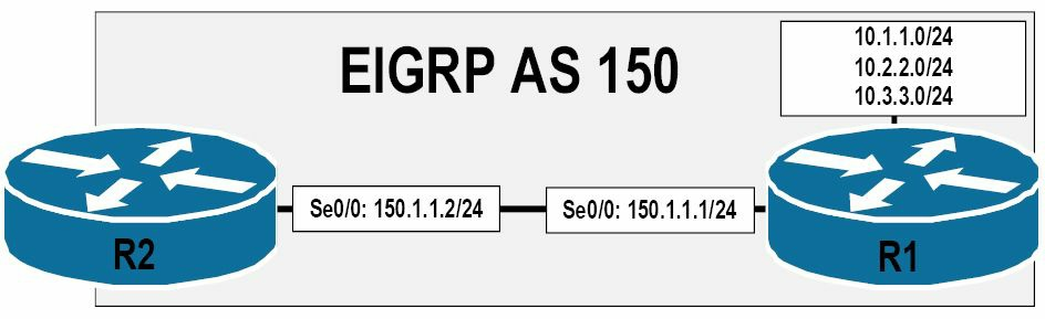 图 36.15 -- EIGRP的自动路由汇总
参考图36.15中的EIGRP网络,路由器R1与R2运行着EIGRP,使用着自治系统编号150。10.1.1.0/24、10.2.2.0/24与10.3.3.3.0/24子网都是直接连接到路由器R1上的。路由器R1正将这些路由通告给R2。路由器R1与R2是使用了一条在150.1.1.0/24子网(该子网是一个与10.1.1.0/24、10.2.2.0/24及10.3.3.3.0/24子网都不相同的主要网络(major network)), 上的背靠背的串行链路连接起来的。根据连接在这些路由器上的网络,默认EIGRP将执行自动汇总,如下所示:
10.1.1.0/24、10.2.2.0/24与10.3.3.3.0/24子网将被汇总到10.0.0.0/8150.1.1.0/24子网将被汇总到150.1.0.0/16
可以查看show ip protocols命令的输出,来对此默认行为进行验证。路由器R1上该命令的输出如下所示:
R1#show ip protocols
Routing Protocol is “eigrp 150”
  Outgoing update filter list for all interfaces is not set
  Incoming update filter list for all interfaces is not set
  Default networks flagged in outgoing updates
  Default networks accepted from incoming updates
  EIGRP metric weight K1=1, K2=0, K3=1, K4=0, K5=0
  EIGRP maximum hopcount 100
  EIGRP maximum metric variance 1
  Redistributing: eigrp 150
  EIGRP NSF-aware route hold timer is 240s
  Automatic network summarization is in effect
  Automatic address summarization:
    150.1.0.0/16 for Loopback1, Loopback2, Loopback3
      Summarizing with metric 2169856
    10.0.0.0/8 for Serial0/0
      Summarizing with metric 128256
  Maximum path: 4
  Routing for Networks:
    10.1.1.0/24
    10.2.2.0/24
    10.3.3.0/24
    150.1.1.0/24
  Routing Information Sources:
    Gateway         Distance      Last Update
    (this router)         90      00:03:12
    150.1.1.2             90      00:03:12
  Distance: internal 90 external 170
在上面的输出中,10.1.1.0/24、10.2.2.0/24与10.3.3.3.0/24子网已被自动汇总到10.0.0.0/8。该汇总地址就被通告出Serial0/0接口。而150.1.1.0/24子网已被汇总到150.1.0.0/16。该汇总地址就被通告出Loopback1、Loopback2与Loopback3这三个环回接口。这里要记住,默认EIGRP将在所有EIGRP路由开启的接口上,发出路由更新(Remember, by default, EIGRP will send out updates on all interfaces for which EIGRP routing is enabled)。
参考上面的打印输出,可以看到环回接口上所发出的更新,就是一种资源的浪费,因为设备是无法物理连接到路由器环回接口上去监听此类更新的(Referencing the output printed above, you can see that sending updates on a Loopback interface is a waste of resource because a device cannot be connected physically to a router Loopback interface listening for such updates)。那么就可以通告使用路由器配置命令passive-interface,来关闭此默认行为,如下所示:
R1(config)#router eigrp 150
R1(config-router)#passive-interface Loopback1
R1(config-router)#passive-interface Loopback2
R1(config-router)#passive-interface Loopback3
R1(config-router)#exit
这样的配置的结果,就是不再往这些环回发出EIGRP数据包了。因此,如下所示,汇总地址就不会在这些接口上通告出去了:
R1#show ip protocols
Routing Protocol is “eigrp 150”
  Outgoing update filter list for all interfaces is not set
  Incoming update filter list for all interfaces is not set
  Default networks flagged in outgoing updates
  Default networks accepted from incoming updates
  EIGRP metric weight K1=1, K2=0, K3=1, K4=0, K5=0
  EIGRP maximum hopcount 100
  EIGRP maximum metric variance 1
  Redistributing: eigrp 150
  EIGRP NSF-aware route hold timer is 240s
  Automatic network summarization is in effect
  Automatic address summarization:
    10.0.0.0/8 for Serial0/0
      Summarizing with metric 128256
  Maximum path: 4
  Routing for Networks:
    10.0.0.0
    150.1.0.0
  Passive Interface(s):
    Loopback0
    Loopback1
    Loopback2
    Loopback3
  Routing Information Sources:
    Gateway         Distance     Last Update
    (this router)         90     00:03:07
    150.1.1.2             90     00:01:12
  Distance: internal 90 external 170
注意: 本课程模块稍后会对
passive-interface命令进行详细讲解。
继续有关自动汇总方面的内容,在对有类边界进行自动汇总后,EIGRP就将一条到汇总地址的路由,安装到EIGRP的拓扑表与IP路由表中(Continuing with automatic summarisation, following automatic summarisation at the classful boundary, EIGRP installs a route to the summary address into the EIGRP topology table and the IP routing table)。下面的EIGRP拓扑表中就包含了此汇总地址的路由,以及更具体的路由条目以及这些路由条目各自所直接连接的接口:
R1#show ip eigrp topology
IP-EIGRP Topology Table for AS(150)/ID(10.3.3.1)
Codes: P - Passive, A - Active, U - Update, Q - Query, R - Reply,
       r - reply Status, s - sia Status
P 10.0.0.0/8, 1 successors, FD is 128256
        via Summary (128256/0), Null0
P 10.3.3.0/24, 1 successors, FD is 128256
        via Connected, Loopback3
P 10.2.2.0/24, 1 successors, FD is 128256
        via Connected, Loopback2
P 10.1.1.0/24, 1 successors, FD is 128256
        via Connected, Loopback1
...
[Truncated Output]
在路由表中,汇总路由是直接连接到Null0接口上的。该路由有着一个默认为5的管理距离数值(a default administrative distance value of 5)。下面的输出对此进行了演示:
R1#show ip route 10.0.0.0 255.0.0.0
Routing entry for 10.0.0.0/8
  Known via “eigrp 150”, distance 5, metric 128256, type internal
  Redistributing via eigrp 150
  Routing Descriptor Blocks:
  * directly connected, via Null0
      Route metric is 128256, traffic share count is 1
      Total delay is 5000 microseconds, minimum bandwidth is 10000000 Kbit
      Reliability 255/255, minimum MTU 1514 bytes
      Loading 1/255, Hops 0
在EIGRP完成自动汇总时,路由器将对汇总路由进行通告,从而抑制了那些更为具体路由的通告(When EIGRP performs automatic summarisation, the router advertises the summary route and suppresses the more specific routes)。换句话说,在汇总路由得以通告时,那些更为具体的前缀,在发往EIGRP邻居的更新中就被省略了(the more specific prefixes are suppressed in updates to EIGRP neighbours)。这一点可通过查看路由器R2上的路由表,加以验证,如下所示:
R2#show ip route eigrp
D    10.0.0.0/8 [90/2298856] via 150.1.1.1, 00:29:05, Serial0/0
这种默认行为在一些基本的网络,比如上图36.15中演示的网络中,运作不错。但其可能在不连续网络--那种由两个分离的主要网络所组成的网络中,如下图36.16中所演示的,有着不利影响(However, it can have an adverse impact in a discontiguous network, which comprises a major network that separates another major network):
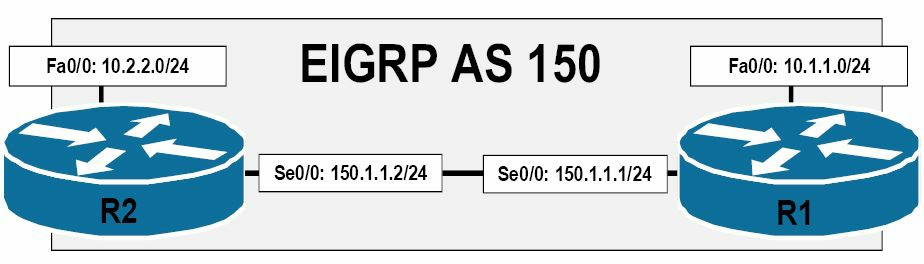 图 36.16 -- 不连续网络, Discontiguous Network
参考图36.16中所演示的图例,一个大的150.1.0.0/16网络将这里的两个大的10.0.0.0/8网络分开了。在开启自动汇总时,路由器R1与R2将把10.1.1.0/24及10.2.2.0/24子网,相应地都汇总到10.0.0.0/8地址。该汇总路由将以下一跳接口Null0,被安装(到路由表中)。而Null0接口又是一个“数位垃圾桶(bit-bucket)”。所有发送到此接口的数据包,就将实实在在地被丢弃。
译者注:本小节及前面小节中所提到的大网络(the major network),是指按网络大类分的网络,也就是A、B、C、D及E类网络。
因为两台路由器就只把汇总地址通告给对方,所以两台路由器都将无法到达对方的10.x.x.x/24子网。为掌握到图36.16所演示网络中自动汇总的衍生问题(ramifications),下面从在路由器R1及R2上的配置开始,一次一步的走一下这些步骤,如下所示:
R1(config)#router eigrp 150
R1(config-router)#network 10.1.1.0 0.0.0.255
R1(config-router)#network 150.1.1.0 0.0.0.255
R1(config-router)#exit
R2(config)#router eigrp 150
R2(config-router)#network 10.2.2.0 0.0.0.255
R2(config-router)#network 150.1.1.0 0.0.0.255
R2(config-router)#exit
因为两台路由器上有类边界处的自动汇总都是默认开启的,所以这两台路由器都将生成两个汇总地址:一个是10.0.0.0/8的,另一个是150.1.0.0/16的(Because automatic summarisation at the classful boundary is enabled by default on both of the routers, they will both generate two summary addresses: one for 10.0.0.0/8 and another for 150.1.0.0/16)。这两个汇总地址都将指向到Null0接口,同时路由器R1上的路由表将显示下面这些条目:
R1#show ip route eigrp
     10.0.0.0/8 is variably subnetted, 2 subnets, 2 masks
D       10.0.0.0/8 is a summary, 00:04:51, Null0
     150.1.0.0/16 is variably subnetted, 2 subnets, 2 masks
D       150.1.0.0/16 is a summary, 00:06:22, Null0
与此类似,路由器R2上反应了同样的情况,如下所示:
R2#show ip route eigrp
     10.0.0.0/8 is variably subnetted, 2 subnets, 2 masks
D       10.0.0.0/8 is a summary, 00:01:58, Null0
     150.1.0.0/16 is variably subnetted, 2 subnets, 2 masks
D       150.1.0.0/16 is a summary, 00:01:58, Null0
虽然汇总地址150.1.0.0/16被安装到了IP路由表中,路由器R1与R2是仍可ping通对方的,因为这里的更为具体路由条目(the more route-specific entry, 150.1.1.0/24)是位处于直连接口之上的。可通过执行show ip route [address] [mask] longer-prefixes命令,来查看到这些某个汇总路由中的详细条目。下面演示了对于150.1.0.0/16汇总,该命令的输出:
R1#show ip route 150.1.0.0 255.255.0.0 longer-prefixes
Codes: C - connected, S - static, R - RIP, M - mobile, B - BGP
       D - EIGRP, EX - EIGRP external, O - OSPF, IA - OSPF inter area
       N1 - OSPF NSSA external type 1, N2 - OSPF NSSA external type 2
       E1 - OSPF external type 1, E2 - OSPF external type 2
       i - IS-IS, su - IS-IS summary, L1 - IS-IS level-1, L2 - IS-IS level-2
       ia - IS-IS inter area, * - candidate default, U - per-user static route
       o - ODR, P - periodic downloaded static route
Gateway of last resort is not set
     150.1.0.0/16 is variably subnetted, 2 subnets, 2 masks
C       150.1.1.0/24 is directly connected, Serial0/0
D       150.1.0.0/16 is a summary, 00:10:29, Null0
因为那条更详细的150.1.1.0/24路由条目是存在的,所以发送到150.1.1.2地址的数据包将经由Serial0/0接口加以转发。这就令到路由器R1与R2的连通性没有问题,如下所示:
R1#ping 150.1.1.2
Type escape sequence to abort.
Sending 5, 100-byte ICMP Echos to 150.1.1.2, timeout is 2 seconds:
!!!!!
Success rate is 100 percent (5/5), round-trip min/avg/max = 1/3/4 ms
但是,那些到这个大的150.1.0.0/16网络的所有其它子网的数据包,都将发送到Null0接口,因为没有其它具体路由条目存在(于路由表中)。
那么到这里,一切都说得通了(So far, everything appears to be in order)。可以看出,因为大的150.1.0.0/16网络的这条更具体路由条目(150.1.1.0/24)的存在,路由器R1与R2之间是能ping通的。不过问题在于路由器R1与R2上大的网络10.0.0.0/8的那些子网。路由器R1(的路由表)显示出下面其生成的10.0.0.0/8汇总地址的具体路由条目:
R1#show ip route 10.0.0.0 255.0.0.0 longer-prefixes
Codes: C - connected, S - static, R - RIP, M - mobile, B - BGP
       D - EIGRP, EX - EIGRP external, O - OSPF, IA - OSPF inter area
       N1 - OSPF NSSA external type 1, N2 - OSPF NSSA external type 2
       E1 - OSPF external type 1, E2 - OSPF external type 2
       i - IS-IS, su - IS-IS summary, L1 - IS-IS level-1, L2 - IS-IS level-2
       ia - IS-IS inter area, * - candidate default, U - per-user static route
       o - ODR, P - periodic downloaded static route
Gateway of last resort is not set
     10.0.0.0/8 is variably subnetted, 2 subnets, 2 masks
C       10.1.1.0/24 is directly connected, FastEthernet0/0
D       10.0.0.0/8 is a summary, 00:14:23, Null0
于此类似,路由器R2(的路由表)显示出其生成的10.0.0.0/8汇总地址的以下具体路由条目:
R2#show ip route 10.0.0.0 255.0.0.0 longer-prefixes
Codes: C - connected, S - static, R - RIP, M - mobile, B - BGP
       D - EIGRP, EX - EIGRP external, O - OSPF, IA - OSPF inter area
       N1 - OSPF NSSA external type 1, N2 - OSPF NSSA external type 2
       E1 - OSPF external type 1, E2 - OSPF external type 2
       i - IS-IS, su - IS-IS summary, L1 - IS-IS level-1, L2 - IS-IS level-2
       ia - IS-IS inter area, * - candidate default, U - per-user static route
       o - ODR, P - periodic downloaded static route
Gateway of last resort is not set
     10.0.0.0/8 is variably subnetted, 2 subnets, 2 masks
C       10.2.2.0/24 is directly connected, FastEthernet0/0
D       10.0.0.0/8 is a summary, 00:14:23, Null0
可以看出,两台路由器都没有到对方的10.x.x.x/24子网的路由。假设在路由器R1尝试往10.2.2.0/24发送数据包时,将使用那个汇总地址,那么数据包就将转发到Null0接口。下面的输出对此进行了演示:
R1#show ip route 10.2.2.0
Routing entry for 10.0.0.0/8
  Known via “eigrp 150”, distance 5, metric 28160, type internal
  Redistributing via eigrp 150
  Routing Descriptor Blocks:
  * directly connected, via Null0
      Route metric is 28160, traffic share count is 1
      Total delay is 100 microseconds, minimum bandwidth is 100000 Kbit
      Reliability 255/255, minimum MTU 1500 bytes
      Loading 1/255, Hops 0
路由器R1将无法ping通R2上的10.x.x.x/24子网,反之亦然,如下所示:
R1#ping 10.2.2.2
Type escape sequence to abort.
Sending 5, 100-byte ICMP Echos to 10.2.2.2, timeout is 2 seconds:
.....
Success rate is 0 percent (0/5)
而要解决这个问题,则有两种方案,如下:
- 在两台路由器上手动配置
10.x.x.x/24的静态路由, Mannually configure static routes for the10.x.x.x/24subnets on both routers - 关闭EIGRP的自动有类网络汇总,Disable EIGRP automatic classful network summarisation
第一个选项是相当简单粗暴基础的(very basic)。但是,静态路由配置不具备可伸缩性,且在大型网络中需要大量费时费力的配置。而第二选项,也就是推荐做法,除了具备伸缩性,比起第一选项只需较少的时间精力。通过执行no auto-summary命令,就可将自动汇总予以关闭(较新版本的IOS中,该特性已被默认关闭了), 如下所示:
R1(config)#router eigrp 150
R1(config-router)#no auto-summary
R1(config-router)#exit
R2(config)#router eigrp 150
R2(config-router)#no auto-summary
R2(config-router)#exit
此配置的结果,就是大的网络上的那些具体子网,在两台路由器上都有通告。不会生成汇总路由,如下所示:
R2#show ip route eigrp
     10.0.0.0/24 is subnetted, 2 subnets
D       10.1.1.0 [90/2172416] via 150.1.1.1, 00:01:17, Serial0/0
这些10.x.x.x/24子网之间的连通性,可使用一个简单的ping操作,加以验证,如下所示:
R2#ping 10.1.1.1 source 10.2.2.2 repeat 10
Type escape sequence to abort.
Sending 10, 100-byte ICMP Echos to 10.1.1.1, timeout is 2 seconds:
Packet sent with a source address of 10.2.2.2
!!!!!!!!!!
Success rate is 100 percent (10/10), round-trip min/avg/max = 1/3/4 ms
在深入讨论手动路由汇总前,重要的是先要知道EIGRP是不会自动对外部网络进行汇总的, 除非某个内部网络将包含在那个汇总中(Before we go into the details pertaining to manual summarisation, it is important to know that EIGRP will not automaticlly summarise external networks unless there is an internal network that will be included in the summary)。为更好地掌握此概念,就要参考下图36.17, 该图片演示了一个基本的EIGRP网络:
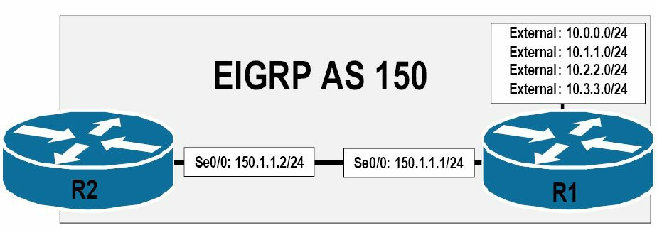 图 36.17 -- 对外部网络的汇总,Summrising External Networks
参考图36.17, 路由器R1正在进行重分发(redistributing, 这令到这些网络成为外部的网络),并在随后将外部网络10.0.0.0/24、10.1.1.0/24、10.2.2.0/24与10.3.3.0/24这些外部网络经由EIGRP进行通告。路由器R1上开启了自动路由汇总。路由器R1上的初始配置是下面这样的:
R1(config)#router eigrp 150
R1(config-router)#redistribute connected metric 8000000 5000 255 1 1514
R1(config-router)#network 150.1.1.1 0.0.0.0
R1(config-router)#exit
show ip protocols命令显示出路由器R1的Serial0/0接口上开启了EIGRP, 同时正通告着那些连接的网络。同时自动汇总是开启的,如下所示:
R1#show ip protocols
Routing Protocol is “eigrp 150”
  Outgoing update filter list for all interfaces is not set
  Incoming update filter list for all interfaces is not set
  Default networks flagged in outgoing updates
  Default networks accepted from incoming updates
  EIGRP metric weight K1=1, K2=0, K3=1, K4=0, K5=0
  EIGRP maximum hopcount 100
  EIGRP maximum metric variance 1
  Redistributing: connected, eigrp 150
  EIGRP NSF-aware route hold timer is 240s
  Automatic network summarization is in effect
  Maximum path: 4
  Routing for Networks:
    150.1.1.1/32
Routing Information Sources:
Gateway             Distance        Last Update
150.1.1.2                 90        00:00:07
  Distance: internal 90 external 170
就像前面输出示例所演示的那样, 因为这些10.x.x.x/24前缀都是外部路由,所以EIGRP不会对这些前缀进行自动汇总。又因此EIGRP不会往拓扑表,也不会往IP路由表中添加一条这些前缀的汇总路由。下面的输出对此进行了演示:
R1#show ip eigrp topology
IP-EIGRP Topology Table for AS(150)/ID(10.3.3.1)
Codes: P - Passive, A - Active, U - Update, Q - Query, R - Reply,
       r - reply Status, s - sia Status
P 10.0.0.0/24, 1 successors, FD is 1280256
        via Rconnected (1280256/0)
P 10.1.1.0/24, 1 successors, FD is 1280256
        via Rconnected (1280256/0)
P 10.2.2.0/24, 1 successors, FD is 1280256
        via Rconnected (1280256/0)
P 10.3.3.0/24, 1 successors, FD is 1280256
        via Rconnected (1280256/0)
...

[Truncated Output]
这些具体路由条目,是作为外部EIGRP路由,通告给路由器R2的,如下所示:
R2#show ip route eigrp
     10.0.0.0/24 is subnetted, 4 subnets
D EX    10.3.3.0 [170/3449856] via 150.1.1.1, 00:07:02, Serial0/0
D EX    10.2.2.0 [170/3449856] via 150.1.1.1, 00:07:02, Serial0/0
D EX    10.1.1.0 [170/3449856] via 150.1.1.1, 00:07:02, Serial0/0
D EX    10.0.0.0 [170/3449856] via 150.1.1.1, 00:07:02, Serial0/0
现在,假设10.0.0.0/24是一个内部网络,而10.1.1.0/24、10.2.2.0/24与10.3.3.0/24三个子网却是外部网络。因为这些将构成有类汇总地址10.0.0.0/8的路由中有一条是内部路由,所以EIGRP将创建出一个汇总地址,并将其包含在EIGRP拓扑表与IP路由表中。命令show ip protocols显示出10.0.0.0/24网络此时就是一个内部EIGRP网络了,如下所示:
R1#show ip protocols
Routing Protocol is “eigrp 150”
  Outgoing update filter list for all interfaces is not set
  Incoming update filter list for all interfaces is not set
  Default networks flagged in outgoing updates
  Default networks accepted from incoming updates
  EIGRP metric weight K1=1, K2=0, K3=1, K4=0, K5=0
  EIGRP maximum hopcount 100
  EIGRP maximum metric variance 1
  Redistributing: connected, eigrp 150
  EIGRP NSF-aware route hold timer is 240s
  Automatic network summarization is in effect
  Automatic address summarization:
    150.1.0.0/16 for Loopback0
      Summarizing with metric 2169856
    10.0.0.0/8 for Serial0/0
      Summarizing with metric 128256
  Maximum path: 4
  Routing for Networks:
    10.0.0.1/32
    150.1.1.1/32
  Routing Information Sources:
    Gateway         Distance        Last Update
    (this router)         90        00:00:05
    150.1.1.2             90        00:00:02
  Distance: internal 90 external 170
在上面的输出中,EIGRP的自动汇总,已经生成一个10.0.0.0/8的汇总地址,因为10.0.0.0/24这个内部子网是该聚合地址(the aggregate address)的一部分。而EIGRP的拓扑表,将显示出这些外部与内部条目,以及生成的汇总地址,如下所示:
R1#show ip eigrp topology
IP-EIGRP Topology Table for AS(150)/ID(10.3.3.1)
Codes: P - Passive, A - Active, U - Update, Q - Query, R - Reply,
       r - reply Status, s - sia Status
P 10.0.0.0/8, 1 successors, FD is 128256
        via Summary (128256/0), Null0
P 10.0.0.0/24, 1 successors, FD is 128256
        via Connected, Loopback0
P 10.1.1.0/24, 1 successors, FD is 1280256
        via Rconnected (1280256/0)
P 10.2.2.0/24, 1 successors, FD is 1280256
        via Rconnected (1280256/0)
P 10.3.3.0/24, 1 successors, FD is 1280256
        via Rconnected (1280256/0)
...

[Truncated Output]
此时,就仅有一条路由通告给路由器R2了,如下面的输出所示:
R2#show ip route eigrp
D    10.0.0.0/8 [90/2297856] via 150.1.1.1, 00:04:05, Serial0/0
从路由器R2的角度看,该路由就是一条简单的内部EIGRP路由。也就是说,路由器R2并不知道这个汇总地址还有着一些外部路由,如下所示:
R2#show ip route 10.0.0.0 255.0.0.0
Routing entry for 10.0.0.0/8
  Known via “eigrp 150”, distance 90, metric 2297856, type internal
  Redistributing via eigrp 150
  Last update from 150.1.1.1 on Serial0/0, 00:05:34 ago
  Routing Descriptor Blocks:
  * 150.1.1.1, from 150.1.1.1, 00:05:34 ago, via Serial0/0
      Route metric is 2297856, traffic share count is 1
      Total delay is 25000 microseconds, minimum bandwidth is 1544 Kbit
      Reliability 255/255, minimum MTU 1500 bytes
      Loading 1/255, Hops 1
经由所接收到的这条汇总路由,路由器R2是可以同时到达这个内部的10.0.0.0/24与那些其它的外部10.x.x.x/24网络,如下所示:
R2#ping 10.0.0.1
Type escape sequence to abort.
Sending 5, 100-byte ICMP Echos to 10.0.0.1, timeout is 2 seconds:
!!!!!
Success rate is 100 percent (5/5), round-trip min/avg/max = 1/2/4 ms

R2#ping 10.3.3.1
Type escape sequence to abort.
Sending 5, 100-byte ICMP Echos to 10.3.3.1, timeout is 2 seconds:
!!!!!
Success rate is 100 percent (5/5), round-trip min/avg/max = 1/3/4 ms
与EIGRP的自动汇总不同,EIGRP的手动路由汇总,是在接口级别使用接口配置命令ip summary-address eigrp [ASN] [network] [mask] [distance] [leak-map <name>],进行配置和部署的。默认情况下,分配给EIGRP汇总地址的默认管理距离值为5(By default, an EIGRP summary address is assigned a default administrative distance value of 5)。可通过由[distance]关键字所指定的数值,从而指定所需的管理距离值,来改变此默认分配的值。
默认在配置了手动路由汇总时,EIGRP将不会就包含在已汇总网络条目中的那些更具体路由条目,进行通告了。可将关键字[leak-map <name>]配置为允许EIGRP路由泄漏,有了此特性,EIGRP就允许那些指定的具体路由条目,与汇总地址一起得以通告。而那些未在泄露图谱中指定的条目,则仍然会被压减(By default, when manual route summarisation is configured, EIGRP will not advertise the more specific route entries that fall within the summarised network entry. The [leak-map <name>] keyword can be configured to allow EIGRP route leaking, wherein EIGRP allows specified specific route entries to be advertised in conjunction with the summary address. Those entries that are not specified in the leak map are still suppressed)。
在对路由进行手动汇总时,重要的是要足够具体(When mannually summarising routes, it is important to be as specific as possible)。否则,所作出的配置将导致与先前所讲到的不连续网络示例中类似的流量黑洞问题。下图36.18中对此概念进行了演示:
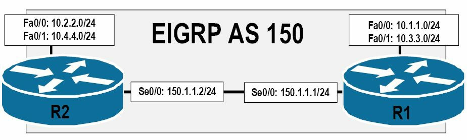 图 36.18 -- 不良路由汇总下的流量黑洞问题,Black-Holing traffic with Poor Route Summarisation
参考图36.18, 假如在两台路由器上都手动配置了一个10.0.0.0/8的汇总地址,那么更为具体的那些前缀就被压减掉了。因为同时EIGRP将一条到该汇总地址的路由,与下一跳接口Null0,安装到EIGRP的拓扑表及IP路由表,那么在此网络中将经历与不连续网络中自动汇总同样的问题,两台路由器上相应子网将无法与对方联系上。
此外,同样重要的是需要明白,如网络中有着不良部署,手动汇总还将导致网络的次优路由问题(suboptimal routing)。下图36.19对此进行了演示:
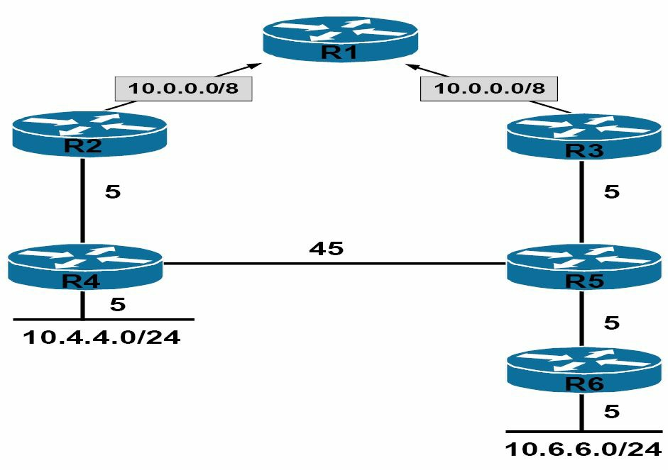 图 36.19 -- 路由汇总带来的次优路由问题,Suboptimal Routing with Route Summarisation
默认情况下,在EIGRP的一条汇总路由创建出来后,路由器就将该汇总地址以其中所有更具体路由度量值中最小的度量值进行通告。也就是说,汇总地址将有着包含在汇总地址建立中最低的、最具体路由的度量值(By default, when a summary route is created for EIGRP, the router advertises the summary address with a metric equal to the minimum of all the more specific routes. In other words, the summary address will have the same metric as the lowest, most specific route included in the creation of the summary address)。
参考图36.19中所演示的网络拓扑,路由器R2与R3都正将汇总地址10.0.0.0/8通告给R1。此汇总是有更具体的10.4.4.0/24与10.6.6.0/24前缀构成的。该汇总地址所使用的度量值,在两台路由器上分别如下表36.5那样计算出来:
表 36.5 -- 汇总路由的度量值计算
| 起始点(路由器) | 到10.4.4.0/24的度量值 |
到10.6.6.0/24的度量值 |
|---|---|---|
R2 |
5+5=10 |
5+45+5+5=60 |
R3 |
5+45+5=55 |
5+5+5=15 |
基于表36.5中的度量值计算, 对于从路由器R1起始的流量,R2显然有着到10.4.4.0的最低度量值路径,同时R3有着对于起始自R1、到10.6.6.0/24网络流量的最低度量值路径。但在汇总地址10.0.0.0/8被通告到路由器R1时,该汇总地址使用了构成该汇总路由的所有路由中最低最小度量值。在这个示例中,路由器R2以度量值10, 将该汇总地址通告给R1。R3以同样逻辑,以15的度量值将该汇总路由通告给R1。
在路由器R1从R2及R3处接收到两条汇总路由后,它将使用最低的度量值来转发那些以包含在大的(主要)有类网络10.0.0.0/8中的那些子网为目的的流量。下图36.20对此进行了演示:
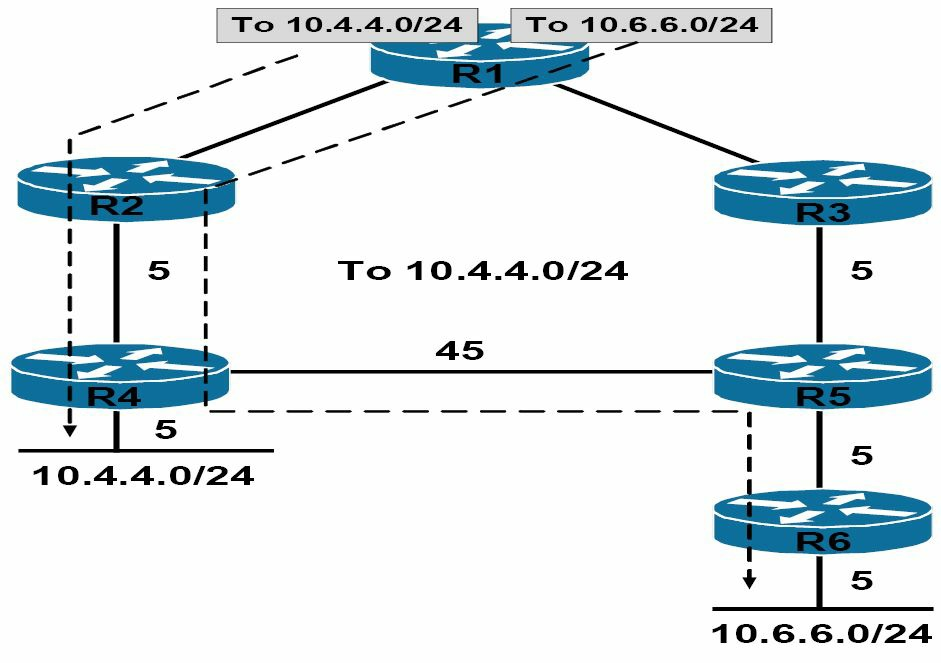 图 36.20 -- 路由汇总下的次优路由,Suboptimal Routing with Route Summarisation
参考图36.20, 可清楚地发现,尽管这对于10.4.4.0/24子网来说,是一条最优路径,而对于10.6.6.0/24子网却是一条次优路径。因此,在网络中部署路由汇总时,先弄清楚网络拓扑是非常重要的。
回到采用EIGRP时的手动路由汇总的配置上,下图36.21所演示的网络拓扑,将用于对手动路由汇总及路由泄露特性(route leaking)的演示:
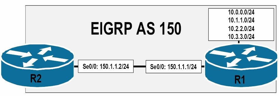 图 36.21 -- EIGRP手动路由汇总的配置,Configuring EIGRP Manual Route Summarisation
基于路由器R1上所配置的接口,R2上的路由表将显示出以下条目:
R2#show ip route eigrp
     10.0.0.0/24 is subnetted, 4 subnets
D       10.3.3.0 [90/2297856] via 150.1.1.1, 00:00:14, Serial0/0
D       10.2.2.0 [90/2297856] via 150.1.1.1, 00:00:14, Serial0/0
D       10.1.1.0 [90/2297856] via 150.1.1.1, 00:00:14, Serial0/0
D       10.0.0.0 [90/2297856] via 150.1.1.1, 00:00:14, Serial0/0
为将路由器R1上的这些路由条目进行汇总并通告出一条单一的特定(译者注,这里可能是“汇总”,而不是具体(specific))路由,就要在R1的Serial0/0接口上应用如下配置:
R1(config)#interface Serial0/0
R1(config-if)#ip summary-address eigrp 150 10.0.0.0 255.252.0.0
R1(config-if)#exit
在此配置下,该汇总条目10.0.0.0/14就将被安装到路由器R1的EIGRP拓扑表与IP路由表中。该EIGRP拓扑表条目如下所示:
R1#show ip eigrp topology
IP-EIGRP Topology Table for AS(150)/ID(10.3.3.1)
Codes: P - Passive, A - Active, U - Update, Q - Query, R - Reply,
       r - reply Status, s - sia Status
P 10.0.0.0/14, 1 successors, FD is 128256
        via Summary (128256/0), Null0
P 10.3.3.0/24, 1 successors, FD is 128256
        via Connected, Loopback3
P 10.2.2.0/24, 1 successors, FD is 128256
        via Connected, Loopback2
P 10.0.0.0/24, 1 successors, FD is 128256
        via Connected, Loopback0
P 10.1.1.0/24, 1 successors, FD is 128256
        via Connected, Loopback1
...
[Truncated Output]
而该路由表条目,也同样反应出来此汇总路由的下一跳接口为Null0, 如下所示:
R1#show ip route
Codes: C - connected, S - static, R - RIP, M - mobile, B - BGP
       D - EIGRP, EX - EIGRP external, O - OSPF, IA - OSPF inter area
       N1 - OSPF NSSA external type 1, N2 - OSPF NSSA external type 2
       E1 - OSPF external type 1, E2 - OSPF external type 2
       i - IS-IS, su - IS-IS summary, L1 - IS-IS level-1, L2 - IS-IS level-2
       ia - IS-IS inter area, * - candidate default, U - per-user static route
       o - ODR, P - periodic downloaded static route
Gateway of last resort is not set
     10.0.0.0/8 is variably subnetted, 5 subnets, 2 masks
C       10.3.3.0/24 is directly connected, Loopback3
C       10.2.2.0/24 is directly connected, Loopback2
C       10.1.1.0/24 is directly connected, Loopback1
C       10.0.0.0/24 is directly connected, Loopback0
D*      10.0.0.0/14 is a summary, 00:02:37, Null0
     150.1.0.0/24 is subnetted, 1 subnets
C       150.1.1.0 is directly connected, Serial0/0
     150.2.0.0/24 is subnetted, 1 subnets
C       150.2.2.0 is directly connected, Serial0/1
可再次使用show ip route [address] [mask] longer-prefixes命令,来查看组成该聚合或者说汇总路由的那些具体路由条目,如下面路由器R1上的输出所示:
R1#show ip route 10.0.0.0 255.252.0.0 longer-prefixes
Codes: C - connected, S - static, R - RIP, M - mobile, B - BGP
       D - EIGRP, EX - EIGRP external, O - OSPF, IA - OSPF inter area
       N1 - OSPF NSSA external type 1, N2 - OSPF NSSA external type 2
       E1 - OSPF external type 1, E2 - OSPF external type 2
       i - IS-IS, su - IS-IS summary, L1 - IS-IS level-1, L2 - IS-IS level-2
       ia - IS-IS inter area, * - candidate default, U - per-user static route
       o - ODR, P - periodic downloaded static route
Gateway of last resort is not set
     10.0.0.0/8 is variably subnetted, 5 subnets, 2 masks
C       10.3.3.0/24 is directly connected, Loopback3
C       10.2.2.0/24 is directly connected, Loopback2
C       10.1.1.0/24 is directly connected, Loopback1
C       10.0.0.0/24 is directly connected, Loopback0
D       10.0.0.0/14 is a summary, 00:04:03, Null0
而在路由器R2上,则接收到汇总地址10.0.0.0/14的一条单一的路由条目,如下所示:
R2#show ip route eigrp
     10.0.0.0/14 is subnetted, 1 subnets
D       10.0.0.0 [90/2297856] via 150.1.1.1, 00:06:22, Serial0/0
为加强该汇总路由度量值概念,这里假设路由器R1上的那些路由都是有着不同度量值的外部路由(也就是说,这些路由是已被重分发到EIGRP中的)。那么R1上的EIGRP拓扑表,将显示以下条目:
R1#show ip eigrp topology
IP-EIGRP Topology Table for AS(150)/ID(10.3.3.1)
Codes: P - Passive, A - Active, U - Update, Q - Query, R - Reply,
       r - reply Status, s - sia Status
P 10.0.0.0/24, 1 successors, FD is 10127872
        via Rconnected (10127872/0)
P 10.1.1.0/24, 1 successors, FD is 3461120
        via Rconnected (3461120/0)
P 10.2.2.0/24, 1 successors, FD is 2627840
        via Rconnected (2627840/0)
P 10.3.3.0/24, 1 successors, FD is 1377792
        via Rconnected (1377792/0)
...
[Truncated Output]
此时再度在路由器R1上做先前示例中的相同汇总地址配置,如下所示:
R1(config)#int s0/0
R1(config-if)#ip summary-address eigrp 150 10.0.0.0 255.252.0.0
R1(config-if)#exit
那么基于此配置,该汇总路由就以它所包含的所有路由中的最小度量值,而放入到EIGRP拓扑表和IP路由表中(Based on this configuration, the summary route is placed into the EIGRP topology table and the IP routing table with a metric equal to the lowest metric of all routes that it encompasses)。而根据前面所展示的show ip eigrp topology命令的输出,该汇总地址将获得到与10.3.3.0/24前缀相同的度量值,如下所示:
R1#show ip eigrp topology
IP-EIGRP Topology Table for AS(150)/ID(10.3.3.1)
Codes: P - Passive, A - Active, U - Update, Q - Query, R - Reply,
    r - reply Status, s - sia Status
P 10.0.0.0/14, 1 successors, FD is 1377792
        via Summary (1377792/0), Null0
P 10.0.0.0/24, 1 successors, FD is 10127872
        via Rconnected (10127872/0)
P 10.1.1.0/24, 1 successors, FD is 3461120
        via Rconnected (3461120/0)
P 10.2.2.0/24, 1 successors, FD is 2627840
        via Rconnected (2627840/0)
P 10.3.3.0/24, 1 successors, FD is 1377792
        via Rconnected (1377792/0)
P 150.1.1.0/24, 1 successors, FD is 2169856
        via Connected, Serial0/0
什么是被动接口
Understanding Passive Interface
如同本课程模块前面所指出的,在对某个网络开启了EIGRP后,路由器就开始在其位于某个特定网络范围内的所有接口上,发出Hello数据包。这样做可令到EIGRP能够动态地发现邻居,并建立各种网络关系。这对于那些切实有着到物理介质连接的接口上,比如以太网及串行接口等,是需要的。但这种默认行为在那些绝不会有其它设备连接的逻辑接口上(logical interfaces),比如环回接口,却是不必要的,因为路由器绝不会经由这些逻辑接口建立EIGRP的邻居关系,相反还会造成不必要的路由器资源浪费。
思科IOS软件允许管理员使用路由器配置命令passive-interface [name|default], 将命名的接口(the named interface)或把所有接口,指定为被动模式。从而不会在这些被动接口上发出EIGRP数据包; 在这些被动接口之间,就绝对不会建立邻居关系了。下面的输出演示了在路由器上如何将两个开启了EIGRP的接口,配置为被动模式:
R1(config)#interface Loopback0
R1(config-if)#ip address 10.0.0.1 255.255.255.0
R1(config-if)#exit
R1(config)#interface Loopback1
R1(config-if)#ip address 10.1.1.1 255.255.255.0
R1(config-if)#exit
R1(config)#interface Serial0/0
R1(config-if)#ip address 150.1.1.1 255.255.255.0
R1(config-if)#exit
R1(config)#router eigrp 150
R1(config-router)#no auto-summary
R1(config-router)#network 150.1.1.0 0.0.0.255
R1(config-router)#network 10.0.0.0 0.0.0.255
R1(config-router)#network 10.1.1.0 0.0.0.255
R1(config-router)#passive-interface Loopback0
R1(config-router)#passive-interface Loopback1
R1(config-router)#exit
基于此种配置,逻辑接口Loopback0与Loopback1是开启了EIGRP路由的,它们上面的直连网络将被通告给EIGRP邻居。但路由器R1是不会将EIGRP数据包从这两个接口发出去的。另一方面,接口Serial0/0上也配置上了EIGRP路由,不过这里是允许EIGRP在此接口上发出数据包的,因为它不是一个被动接口。所有三个网络都是安装到EIGRP路由表中的,如下所示:
R1#show ip eigrp topology
IP-EIGRP Topology Table for AS(150)/ID(10.3.3.1)
Codes: P - Passive, A - Active, U - Update, Q - Query, R - Reply,
       r - reply Status, s - sia Status
P 10.1.1.0/24, 1 successors, FD is 128256
        via Connected, Loopback1
P 10.0.0.0/24, 1 successors, FD is 128256
        via Connected, Loopback0
P 150.1.1.0/24, 1 successors, FD is 2169856
        via Connected, Serial0/0
但show ip eigrp interfaces显示EIGRP路由只是对Serial0/0接口是开启的,如下所示:
R1#show ip eigrp interfaces
IP-EIGRP interfaces for process 150
                      Xmit Queue   Mean    Pacing Time     Multicast     Pending
Interface      Peers  Un/Reliable  SRTT    Un/Reliable     Flow Timer    Routes
Se0/0            1        0/0        0        0/15             0            0
也可在show ip protocols命令的输出中查看到那些配置为被动模式的接口,如下所示:
R1#show ip protocols
Routing Protocol is “eigrp 150”
  Outgoing update filter list for all interfaces is not set
  Incoming update filter list for all interfaces is not set
  Default networks flagged in outgoing updates
  Default networks accepted from incoming updates
  EIGRP metric weight K1=1, K2=0, K3=1, K4=0, K5=0
  EIGRP maximum hopcount 100
  EIGRP maximum metric variance 1
  Redistributing: eigrp 150
  EIGRP NSF-aware route hold timer is 240s
  Automatic network summarization is not in effect
  Maximum path: 4
  Routing for Networks:
    10.0.0.0/24
    10.1.1.0/24
    150.1.1.0/24
  Passive Interface(s):
    Loopback0
    Loopback1
  Routing Information Sources:
    Gateway         Distance      Last Update
  Distance: internal 90 external 170
路由器配置命令passive-interface [name|default]中的[default]关键字令到所有接口,都成为被动模式。先假设路由器上配置了50个的环回接口。如打算将每个环回接口都配置为被动模式,那么就需要50行的代码。而这时就可以使用passive-interface default命令,来令到所有接口都成为被动接口了。对于那些确实想要发出EIGRP数据包的接口,就可使用no passive-interface [name]命令进行配置。下面对passive-interface default命令的用法进行了演示:
R1(config)#interface Loopback0
R1(config-if)#ip address 10.0.0.1 255.255.255.0
R1(config-if)#exit
R1(config)#interface Loopback1
R1(config-if)#ip address 10.1.1.1 255.255.255.0
R1(config-if)#exit
R1(config)#interface Loopback3
R1(config-if)#ip address 10.3.3.1 255.255.255.0
R1(config-if)#exit
R1(config)#interface Loopback2
R1(config-if)#ip address 10.2.2.1 255.255.255.0
R1(config-if)#exit
R1(config)#interface Serial0/0
R1(config-if)#ip address 150.1.1.1 255.255.255.0
R1(config-if)#exit
R1(config-router)#network 10.0.0.1 255.255.255.0
R1(config-router)#network 10.1.1.1 255.255.255.0
R1(config-router)#network 10.3.3.1 255.255.255.0
R1(config-router)#network 10.2.2.1 255.255.255.0
R1(config-router)#network 150.1.1.1 255.255.255.0
R1(config-router)#passive-interface default
R1(config-router)#no passive-interface Serial0/0
R1(config-router)#exit
这里可以再度使用show ip protocols命令,来查看哪些接口是处于EIGRP下的被动模式的,如下所示:
R1#show ip protocols
Routing Protocol is “eigrp 150”
  Outgoing update filter list for all interfaces is not set
  Incoming update filter list for all interfaces is not set
  Default networks flagged in outgoing updates
  Default networks accepted from incoming updates
  EIGRP metric weight K1=1, K2=0, K3=1, K4=0, K5=0
  EIGRP maximum hopcount 100
  EIGRP maximum metric variance 1
  Redistributing: eigrp 150
  EIGRP NSF-aware route hold timer is 240s
  Automatic network summarization is not in effect
  Maximum path: 4
  Routing for Networks:
    10.0.0.0/24
    10.1.1.0/24
    10.2.2.0/24
    10.3.3.0/24
    150.1.1.0/24
  Passive Interface(s):
    Loopback1
    Loopback2
    Loopback3
    Loopback4
  Routing Information Sources:
    Gateway         Distance       Last Update
    (this router)         90       00:02:52
  Distance: internal 90 external 170
这里通过使用passive-interface default命令,令到多个被动接口的配置就得以简化,并减少了代码。而当其与no passive-interface Serial0/0一起使用时,EIGRP数据包仍旧在接口Serial0/0上发出,从而允许EIGRP邻居关系通过此接口建立起来,如下所示:
R1#show ip eigrp neighbors
IP-EIGRP neighbors for process 150
H   Address      Interface  Hold  Uptime    SRTT  RTO    Q      Seq
                            (sec)           (ms)         Cnt    Num
0   150.1.1.2    Se0/0      12    00:02:47  1     3000   0      69
掌握EIGRP路由器ID的用法
Understanding the Use of the EIGRP Router ID
与OSPF使用路由器ID(the router ID, RID)来识别OSPF邻居不同,EIGRP的RID主要用途是阻止路由环回的形成。RID被用于识别那些外部路由的起源路由器(the primary use of the EIGRP RID is to prevent routing loops. The RID is used to identify the originating router for external routes)。假如接收到一条有着与本地路由器一致的RID外部路由,那么就会将其丢弃。设计此特性的目的,就是降低那些其中有着多台自治系统边界路由器(AS Boundary Router, ASBR)正进行路由重分发的网络中,出现路由环回的可能性。
在确定RID时,EIGRP将选取路由器上所配置的IP地址中最高的作为RID。但如果在路由器上配置了环回接口,那么将优先选取这些接口,因为环回接口是路由器上存在的最稳定接口。除非将EIGRP进程移除,那么RID随后就绝不会变化了(也就是,假如RID是手动配置的情况)。RID始终会在EIGRP拓扑表中列出,如下所示:
R1#show ip eigrp topology
IP-EIGRP Topology Table for AS(150)/ID(10.3.3.1)
Codes: P - Passive, A - Active, U - Update, Q - Query, R - Reply,
       r - reply Status, s - sia Status
P 10.2.2.0/24, 1 successors, FD is 128256
        via Connected, Loopback2
P 10.3.3.0/24, 1 successors, FD is 128256
        via Connected, Loopback3
P 10.1.1.0/24, 1 successors, FD is 128256
        via Connected, Loopback1
P 10.0.0.0/24, 1 successors, FD is 128256
        via Connected, Loopback0
P 150.1.1.0/24, 1 successors, FD is 2169856
        via Connected, Serial0/0
注意: 这里重要的是掌握到RID与邻居ID通常是不同的,然而这对于那些比如只有一个接口的路由器可能不适用。(It is important to understand that the RID and the neighbour ID will typically be different, although this may not be the case in routers with a single interface, for example)。
EIGRP的路由器ID(RID)是通过路由器配置命令eigrp router-id [address]进行配置的。在输入了此命令后,RID就以这个新地址,在EIGRP的拓扑表中得以更新。为对此进行演示,这里就以查看路由器上的当前RID开始,如下面的拓扑表中所指出的:
R1#show ip eigrp topology
IP-EIGRP Topology Table for AS(150)/ID(10.3.3.1)
Codes: P - Passive, A - Active, U - Update, Q - Query, R - Reply,
       r - reply Status, s - sia Status
...
[Truncated Output]
现在路由器上配置一个1.1.1.1的RID,如下所示:
R1(config)#router eigrp 150
R1(config-router)#eigrp router-id 1.1.1.1
R1(config-router)#
*Mar 1 05:50:13.642: %DUAL-5-NBRCHANGE: IP-EIGRP(0) 150: Neighbor 150.1.1.2 (Serial0/0) is down: route configuration changed
*Mar 1 05:50:16.014: %DUAL-5-NBRCHANGE: IP-EIGRP(0) 150: Neighbor 150.1.1.2 (Serial0/0) is up: new adjacency
伴随这个改变,EIGRP邻居关系就被重置了,同时在EIGRP拓扑表中立即反映出了这个新的RID,如下所示:
R1#show ip eigrp topology
IP-EIGRP Topology Table for AS(150)/ID(1.1.1.1)
Codes: P - Passive, A - Active, U - Update, Q - Query, R - Reply,
       r - reply Status, s - sia Status
...
[Truncated Output]
在对EIGRP的路由器ID(RID)进行配置时,应记住下面两点:
- 不能(无法)将RID配置为
0.0.0.0 - 不能(无法)将RID配置为
255.255.255.255
现在,源自该路由器的所有外部路由,就都包含了这个EIGRP路由器ID了。在下面的邻居路由器R2输出中,就可对此进行验证:
R2#show ip eigrp topology 192.168.254.0/24
IP-EIGRP (AS 150): Topology entry for 192.168.254.0/24
  State is Passive, Query origin flag is 1, 1 Successor(s), FD is 7289856
  Routing Descriptor Blocks:
  150.1.1.1 (Serial0/0), from 150.1.1.1, Send flag is 0x0
      Composite metric is (7289856/6777856), Route is External
      Vector metric:
        Minimum bandwidth is 1544 Kbit
        Total delay is 220000 microseconds
        Reliability is 255/255
        Load is 1/255
        Minimum MTU is 1500
        Hop count is 1
      External data:
        Originating router is 1.1.1.1
        AS number of route is 0
        External protocol is Connected, external metric is 0
        Administrator tag is 0 (0x00000000)
而对于内部EIGRP路由,则是不包含RID的,如下面的输出所示:
R2#show ip eigrp topology 10.3.3.0/24
IP-EIGRP (AS 150): Topology entry for 10.3.3.0/24
  State is Passive, Query origin flag is 1, 1 Successor(s), FD is 2297856
  Routing Descriptor Blocks:
  150.1.1.1 (Serial0/0), from 150.1.1.1, Send flag is 0x0
      Composite metric is (2297856/128256), Route is Internal
      Vector metric:
      Minimum bandwidth is 1544 Kbit
      Total delay is 25000 microseconds
      Reliability is 255/255
      Load is 1/255
      Minimum MTU is 1500
      Hop count is 1
第36天问题
- You can see the ASN with the
show ip _______command. - Every router you want to communicate with in your routing domain must have a different ASN. True or false?
- What is the purpose of the EIGRP topology table?
- By default, EIGRP uses the
_______bandwidth on the path to a destination network and the total_______to compute routing metrics. - Dynamic neighbour discovery is performed by sending EIGRP Hello packets to the destination Multicast group address
_______. - EIGRP packets are sent directly over IP using protocol number
_______. - To populate the topology table, EIGRP runs the
_______algorithm. - The
______________includes both the metric of a network as advertised by the connected neighbour, plus the cost of reaching that particular neighbour. - Cisco IOS software supports equal cost load sharing for a default of up to four paths for all routing protocols. True or false?
- What EIGRP command can be used to enable unequal cost load sharing?
第36天问题答案
protocols.- False.
- The topology table allows all EIGRP routers to have a consistent view of the entire network. All known destination networks and subnets that are advertised by neighbouring EIGRP routers are stored there.
- Minimum, delay.
224.0.0.10.-
- DUAL.
- Feasible Distance.
- True.
- The
variancecommand.
第36天实验
EIGRP的实验
拓扑图
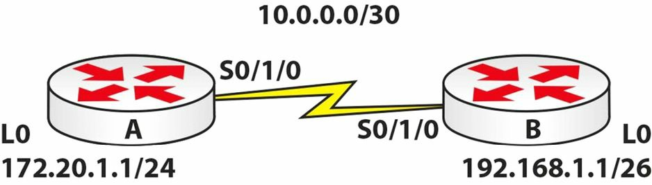
实验目的
学习如何配置基本的EIGRP。
实验步骤
- 基于上面的拓扑,配置上所有IP地址。确保可以经由串行链路
ping通。 - 在两台路由器上以自治系统编号30, 配置EIGRP。
RouterA(config)#router eigrp 30
RouterA(config-router)#net 172.20.0.0
RouterA(config-router)#net 10.0.0.0
RouterA(config-router)#^Z
RouterA#
RouterB#conf t
Enter configuration commands, one per line.
End with CNTL/Z.
RouterB(config)#router eigrp 30
RouterB(config-router)#net 10.0.0.0
%DUAL-5-NBRCHANGE: IP-EIGRP 30: Neighbor 10.0.0.1 (Serial0/1/0) is up: new adjacency
RouterB(config-router)#net 192.168.1.0
- 对两台路由器上的路由表分别进行检查。
RouterA#sh ip route
Codes: C - connected, S - static, I - IGRP, R - RIP, M - mobile, B - BGP
       D - EIGRP, EX - EIGRP external, O - OSPF, IA - OSPF inter area
       N1 - OSPF NSSA external type 1, N2 - OSPF NSSA external type 2
       E1 - OSPF external type 1, E2 - OSPF external type 2, E - EGP
       i - IS-IS, L1 - IS-IS level-1, L2 - IS-IS level-2, ia - IS-IS inter area
       * - candidate default, U - per-user static route, o - ODR
       P - periodic downloaded static route
Gateway of last resort is not set
     10.0.0.0/8 is variably subnetted, 2 subnets, 2 masks
D       10.0.0.0/8 is a summary, 00:01:43, Null0
C       10.0.0.0/30 is directly connected, Serial0/1/0
     172.20.0.0/16 is variably subnetted, 2 subnets, 2 masks
D       172.20.0.0/16 is a summary, 00:01:43, Null0
C       172.20.1.0/24 is directly connected, Loopback0
D    192.168.1.0/24 [90/20640000] via 10.0.0.2, 00:00:49, Serial0/1/0
RouterA#
RouterB#show ip route
...
[Truncated Output]
...
     10.0.0.0/8 is variably subnetted, 2 subnets, 2 masks
D       10.0.0.0/8 is a summary, 00:01:21, Null0
C       10.0.0.0/30 is directly connected, Serial0/1/0
D    172.20.0.0/16 [90/20640000] via 10.0.0.1, 00:01:27, Serial0/1/0
     192.168.1.0/24 is variably subnetted, 2 subnets, 2 masks
D       192.168.1.0/24 is a summary, 00:01:21, Null0
C       192.168.1.0/26 is directly connected, Loopback0
RouterB#
- 查明两台路由器都对各个网络进行着自动汇总。并于随后在路由器B上关闭自动汇总。
RouterB#show ip protocols
Routing Protocol is “eigrp 30”
  Outgoing update filter list for all interfaces is not set
  Incoming update filter list for all interfaces is not set
  Default networks flagged in outgoing updates
  Default networks accepted from incoming updates
  EIGRP metric weight K1=1, K2=0, K3=1, K4=0, K5=0
  EIGRP maximum hopcount 100
  EIGRP maximum metric variance 1
Redistributing: eigrp 30
  Automatic network summarization is in effect
  Automatic address summarization:
    192.168.1.0/24 for Serial0/1/0
      Summarizing with metric 128256
    10.0.0.0/8 for Loopback0
      Summarizing with metric 20512000
  Maximum path: 4
  Routing for Networks:
     10.0.0.0
     192.168.1.0
  Routing Information Sources:
    Gateway         Distance      Last Update
    10.0.0.1        90            496078
  Distance: internal 90 external 170
RouterB(config)#router eigrp 30
RouterB(config-router)#no auto-summary
- 对路由器A上的路由表进行检查。
RouterA#show ip route
...
[Truncated Output]
...
Gateway of last resort is not set
     10.0.0.0/8 is variably subnetted, 2 subnets, 2 masks
D       10.0.0.0/8 is a summary, 00:00:04, Null0
C       10.0.0.0/30 is directly connected, Serial0/1/0
     172.20.0.0/16 is variably subnetted, 2 subnets, 2 masks
D       172.20.0.0/16 is a summary, 00:00:04, Null0
C       172.20.1.0/24 is directly connected, Loopback0
     192.168.1.0/26 is subnetted, 1 subnets
D       192.168.1.0 [90/20640000] via 10.0.0.2, 00:00:04, Serial0/1/0
RouterA#
请访问www.in60days.com,免费观看作者完成此试验。