17 KiB
How I made an automated Jack-o'-lantern with a Raspberry Pi
Here's my recipe for the perfect pumpkin Pi.

It's almost Halloween, one of my favorite days and party times. This year, I decided to (pumpkin) spice up some of my decorations with automated motion sensing. This spooktacular article shows you how I made them, step by step, from building and wiring to coding. This is not your average weekend project—it takes a lot of supplies and building time. But it's a fun way to play around with Raspberry Pi and get in the spirit of this haunting holiday.
What you need for this project
- One large plastic pumpkin
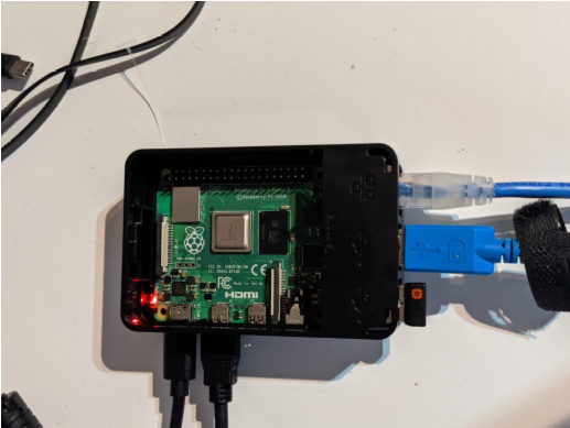
- One Raspberry Pi 4 (with peripherals)
- One Arduino starter kit that works with Raspberry Pi
- One hot glue gun
- Ribbon, ideally in holiday theme colors
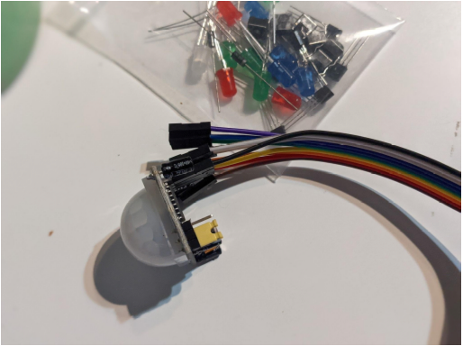
The items you'll need in the starter kit are one infrared motion sensor, a breadboard, two small LED lights, a ribbon to connect the breadboard to the Raspberry Pi, and cabling to configure all of these pieces together. You can find each of these items online, and I suggest the starter kit for the entertaining things you can do beyond this project.
Jess Cherry CC BY-SA 4.0
Jess Cherry CC BY-SA 4.0
Jess Cherry CC BY-SA 4.0
Installing the Raspberry Pi OS and preconfiguration
After receiving my Pi, including the SD card, I went online and followed the Raspberry Pi imager instructions. This allowed for quick installation of the OS onto the SD card. Note: you need the ability to put the SD card in an SD card-reader slot. I have an external attached SD card reader, but some computers have them built in. On your local computer, you also need a VNC viewer.
After installing the OS and running updates, I had some extra steps to get everything to work correctly. To do this, you'll need the following:
- Python 3
- Python3-devel
- Pip
- RPi GPIO (pip install RPi.GPIO)
- A code editor (Thonny is on the Raspberry Pi OS)
Next, set up a VNCviewer, so you can log in when you have the Pi hidden in your pumpkin.
To do this, run the below command, then follow the instructions below.
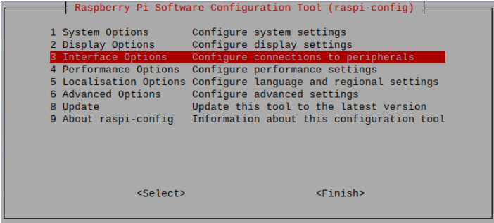
sudo raspi-config
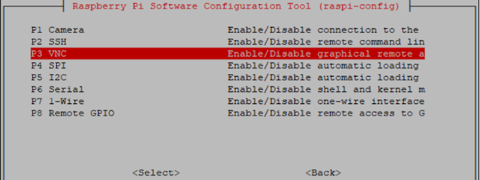
When this menu pops up, choose Interface Options:
Jess Cherry CC BY-SA 4.0
Next, choose VNC and enable it on the pop-up:
Jess Cherry CC BY-SA 4.0
You can also use Secure Shell (SSH) for this, but during the troubleshooting phase, I used VNC. When logged into your Raspberry Pi, gather the IP address and use it for SSH and a VNC connection. If you've moved rooms, you can also use your router or WiFi switch to tell you the IP address of the Pi.
Now that everything is installed, you can move on to building your breadboard with lights.
Everyone should try pumpkin bread(board)
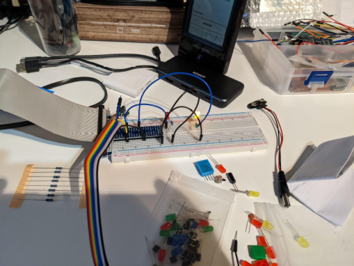
Many people haven't seen or worked with a breadboard, so I've added pictures of my parts, starting with my base components.
Jess Cherry CC BY-SA 4.0
Jess Cherry CC BY-SA 4.0
These two pieces are put together with the extension shield in the center, as shown.
Jess Cherry CC BY-SA 4.0
The ribbon connects to the pin slot in the Raspberry Pi, making the board a new extension we can code and play with. The ribbon isn't required, it's just makes working with the GPIO pins convenient. If you don't want to purchase a ribbon, you can connect female-to-male jumper cables directly from the pins on the Pi to the breadboard. Here are the components you need:
- Raspberry Pi (version 4 or 3)
- Breadboard
- GPIO expansion ribbon cable
- Jumper cables (x6 male-to-male)
- Resistor 220Ω
- HC-SR501 or any similar proximity sensor (x1)
- LED (x2)
Putting the board together
Once you have all of the pieces, you can put everything together. First, take a look at how the pins are defined on the board. This is my personal extension board; the one you have may be different. The pin definitions matter when you get to coding, so keep very good track of your cabling. Below is the schematic of my extension.
As you can see, the schematic has both the defined BCM (Broadcom SOC Channel) GPIO numbering on the physical board and the physical numbering you use within the code to create routines and functions.
Jess Cherry CC BY-SA 4.0
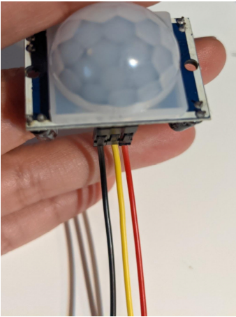
Now it's time to connect some cabling. First, start with the sensor. I was provided with cables to connect in my kit, so I'll add pictures as I go. This is the sensor with a power(+) ground(-) and sensor connection to extension board(s).
Jess Cherry CC BY-SA 4.0
For the cable colors: power is red, ground is black, and yellow carries the sensor data.
Jess Cherry CC BY-SA 4.0
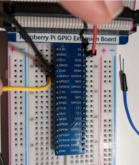
I plug in the cables with power/red to the 5V pin, ground/black to the GRN pin, and sensor/yellow to the GPIO 17 pin, later to be defined as 11 in the code.
Jess Cherry CC BY-SA 4.0
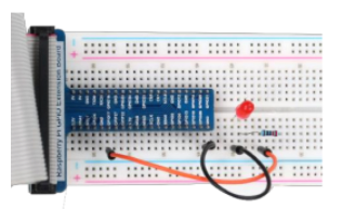
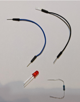
Next, it's time to set up the lights. Each LED light has two pins, one shorter than the other. The long side (anode) always lines up with the pin cable, and the shorter (cathode) with the ground and resistor.
Jess Cherry CC BY-SA 4.0
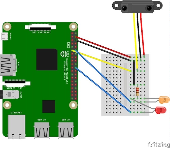
For the first light, I use GPIO18 (pin 12) and GPIO25 for the signal. This is important because the code communicates with these pins. You can change which pin you use, but then you must change the code. Here's a diagram of the end result:
Jess Cherry CC BY-SA 4.0
Now that everything is cabled up, it's time to start working on the code.
How to use a snake to set up a pumpkin
If you've already installed Python 3, you have everything you need to start working through this line by line. In this example, I am using Python 3 with the RPI package. Start with the imported packages, RPI and time from sleep (this helps create the flicker effect described later in the tutorial). I called my Python file senseled.py, but you can name your file whatever you want.
#!/usr/bin/env python3

import RPi.GPIO as GPIO
import os
from time import sleep
Next, define your two LED pins and sensor pin. Earlier in this post, I provided these pin numbers while wiring the card, so you can see those exact numbers below.
ledPin1 = 12 # define ledPins
ledPin2 = 22
sensorPin = 11 # define sensorPin
Since you have two lights to set up to flicker together in this example, I also created a defined array to use later:
leds = [ledPin1, ledPin2]
Next, define the setup of the board and pins using the RPi.GPIO package. To do this, set the mode on the board. I chose to use the physical numbering system in my setup, but you can use the BCM if you prefer. Remember that you can never use both. Here's an example of each:
# for GPIO numbering, choose BCM
GPIO.setmode(GPIO.BCM)

# or, for pin numbering, choose BOARD
GPIO.setmode(GPIO.BOARD)
For this example, use the pin numbering in my setup. Set the two pins to output mode, which means all commands output to the lights. Then, set the sensor to input mode so that as the sensor sees movement, it inputs the data to the board to output the lights. This is what these definitions look like:
def setup():
 GPIO.setmode(GPIO.BOARD) # use PHYSICAL GPIO Numbering
 GPIO.setup(ledPin1, GPIO.OUT) # set ledPin to OUTPUT mode
 GPIO.setup(ledPin2, GPIO.OUT) # set ledPin to OUTPUT mode
 GPIO.setup(sensorPin, GPIO.IN) # set sensorPin to INPUT mode
Now that the board and pins are defined, you can put together your main function. For this, I use the array in a for loop, then an if statement based on the sensor input. If you are unfamiliar with these functions, you can check out this quick guide.
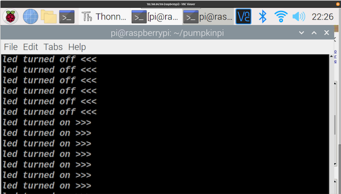
If the sensor receives input, the LED output is high (powered on) for .03 seconds, then low (powered off) while printing the message led turned on. If the sensor receives no input, the LEDs are powered down while printing the message led turned off.
def main():
 while True:
 for led in leds:
 if GPIO.input(sensorPin)==GPIO.HIGH:
 GPIO.output(led, GPIO.HIGH)
 sleep(.05)
 GPIO.output(led, GPIO.LOW)
 print ('led turned on >>>')
 else :
 GPIO.output(led, GPIO.LOW) # turn off led
 print ('led turned off <<<')
While you can mathematically choose the brightness level, I found it easier to set the sleep timer between powering on and powering off. I set this after many tests of the amount of time needed to create a flickering candle effect.
Finally, you need some clean up to release your resources when the program is ended:
def destroy():
 GPIO.cleanup() # Release GPIO resource
Now that everything has been defined to run, you can run your code. Start the program, run the setup, try your main, and if a KeyboardInterrupt is received, destroy and clean everything up.
if __name__ == '__main__': # Program entrance
 print ('Program is starting...')
 setup()
 try:
 main()
 except KeyboardInterrupt: # Press ctrl-c to end the program.
 destroy()
Now that you've created your program, the final result should look like this:
#!/usr/bin/env python3

import RPi.GPIO as GPIO
import os
from time import sleep

ledPin1 = 12 # define ledPins
ledPin2 = 22
sensorPin = 11 # define sensorPin
leds = [ledPin1, ledPin2]

def setup():
 GPIO.setmode(GPIO.BOARD) # use PHYSICAL GPIO Numbering
 GPIO.setup(ledPin1, GPIO.OUT) # set ledPin to OUTPUT mode
 GPIO.setup(ledPin2, GPIO.OUT) # set ledPin to OUTPUT mode
 GPIO.setup(sensorPin, GPIO.IN) # set sensorPin to INPUT mode


def main():
 while True:
 for led in leds:
 if GPIO.input(sensorPin)==GPIO.HIGH:
 GPIO.output(led, GPIO.HIGH)
 sleep(.05)
 GPIO.output(led, GPIO.LOW)
 print ('led turned on >>>')
 else :
 GPIO.output(led, GPIO.LOW) # turn off led
 print ('led turned off <<<')


def destroy():
 GPIO.cleanup() # Release GPIO resource

if __name__ == '__main__': # Program entrance
 print ('Program is starting...')
 setup()
 try:
 main()
 except KeyboardInterrupt: # Press ctrl-c to end the program.
 destroy()
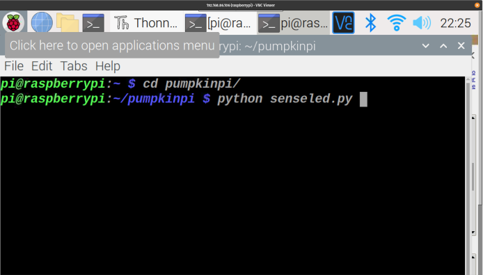
When it runs, it should look similar to this. (Note: I was still testing with sleep time during this recording.)
Time to bake that pumpkin
To start, I had a very large plastic pumpkin gifted by our family to my husband and me.
Jess Cherry CC BY-SA 4.0
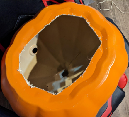
Originally, it had a plug in the back with a bulb that was burnt out, which is what inspired this idea in the first place. I realized I'd have to make some modifications, starting with cutting a hole in the bottom using a drill and jab saw.
Jess Cherry CC BY-SA 4.0
Jess Cherry CC BY-SA 4.0
Luckily, the pumpkin already had a hole in the back for the cord leading to the original light. I could stuff all the equipment inside the pumpkin, but I needed a way to hide the sensor.
First, I had to make a spot for the sensor to be wired externally to the pumpkin, so I drilled a hole by the stem:
Jess Cherry CC BY-SA 4.0
Then I put all the wiring for the sensor through the hole, which ended up posing another issue: the sensor is big and weird-looking. I went looking for a decorative way to resolve this.
Jess Cherry CC BY-SA 4.0
I did, in fact, make the scariest ribbon decoration (covered in hot glue gun mush) in all of humanity, but you won't notice the sensor.
Jess Cherry CC BY-SA 4.0
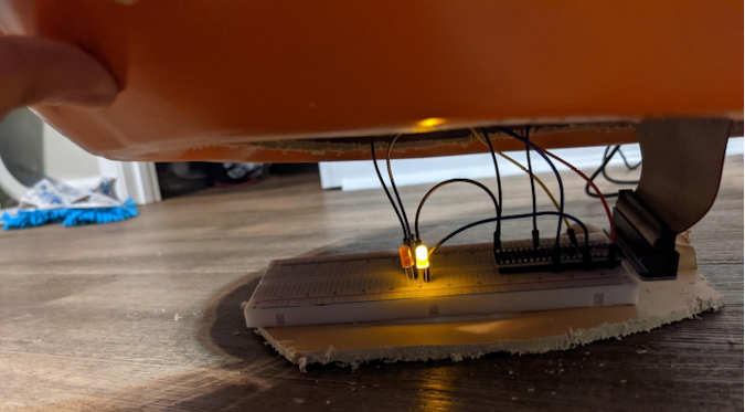
Finally, I put the Pi and extension card in the pumpkin and cabeled the power through the back.
Jess Cherry CC BY-SA 4.0
With everything cabled, I was ready to VNC into my Pi and turn on the Python, then wait for something to move to test it out.
Jess Cherry CC BY-SA 4.0
Jess Cherry CC BY-SA 4.0
Post baking notes
This was a really long and very researched build. As I said in the introduction, this isn't a weekend project. I knew nothing about breadboards when I started, and it took me a while to recode and determine exactly what I wanted. There are some very granular details I did not include here. For example, the sensor has two knobs that define how far it can pick up motion and how long the sensor input needs to continue. While this was a fantastic thing to learn, I would definitely do a lot of research before pursuing this journey.
I did not get to one part of the project that I really wanted: the ability to connect to a Bluetooth device and make spooky noises. That said, playing with a Raspberry Pi is always fun to do, whether with home automation, weather tracking, or just silly decorations. I hope you enjoyed this walk-through and feel inspired to try something similar yourself.
via: https://opensource.com/article/21/10/halloween-raspberry-pi
作者:Jessica Cherry 选题:lujun9972 译者:译者ID 校对:校对者ID
