14 KiB
Build a home thermostat with a Raspberry Pi
The ThermOS project is an answer to the many downsides of off-the-shelf
smart thermostats.

My wife and I moved into a new home in October 2020. As soon as it started getting cold, we realized some shortcomings of the home's older heating system (including one heating zone that was always on). We had Nest thermostats in our previous home, and the current setup was not nearly as convenient. There are multiple thermostats in our house, and some had programmed heating schedules, others had different schedules, some had none at all.
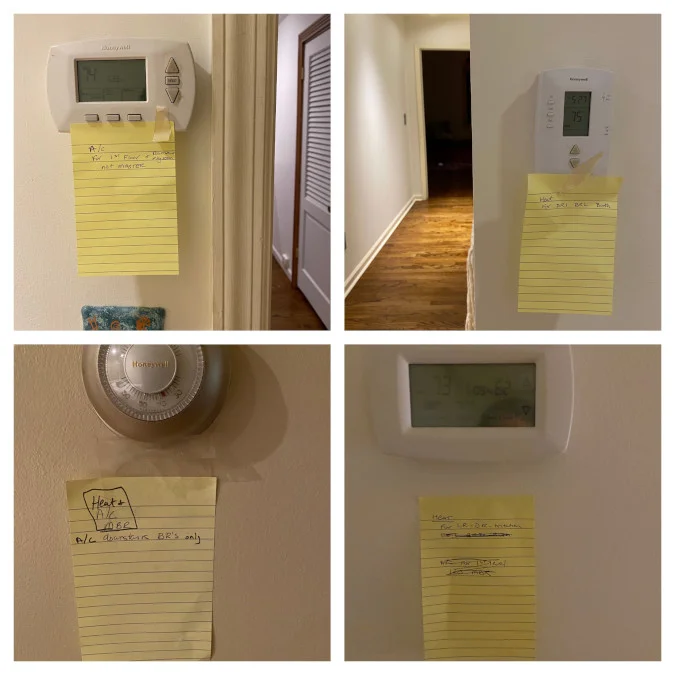
The home's previous owner left notes explaining how some of the thermostats worked. (Joseph Truncale, CC BY-SA 4.0)
It was time for a change, but the house has some constraints:
- It was built in the late 1960s with a renovation during the '90s.
- The heat is hydronic (hot water baseboard).
- It has six thermostats for the six heating zones.
- There are only two wires that go to each thermostat for heat (red and white).
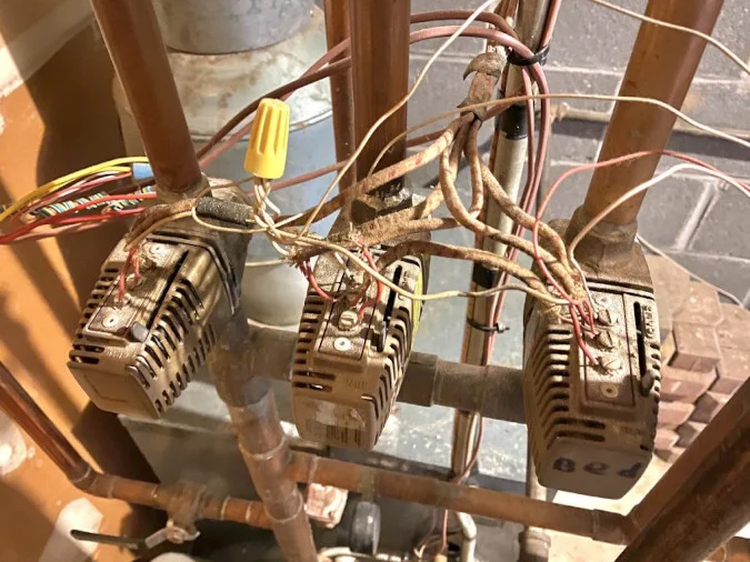
Taco (pronounced TAY-KO) zone valves at the furnace. (Joseph Truncale, CC BY-SA 4.0)
To buy or to build?
I wanted "smart" thermostat control for all of the heat zones (schedules, automations, home/away, etc.). I had several options if I wanted to buy something off the shelf, but all of them have drawbacks:
Option 1: A Nest or Ecobee
- It's expensive: No smart thermostat can handle multiple zones, so I would need one for each zone (~$200*6 = $1,200).
- It's difficult: I would have to rerun the thermostat wire to get the infamous C wire, which enables continuous power to the thermostat. The wires are 20 to 100 feet each, in-wall, and might be stapled to the studs.
Option 2: A battery-powered thermostat such as the Sensi WiFi thermostat
- The batteries last only a month or two.
- It's not HomeKit-compatible in battery-only mode.
Option 3: A commercial-off-the-shelf thermostat, but only one exists (kind of): Honeywell's TrueZONE
- It's old and poorly supported (it was released in 2008).
- It's expensive—more than $300 for just the controller, and you need a RedLINK gateway for a shoddy app to work.
And the winner is…
Option 4: Build my own! I decided to build my own multizone smart thermostat, which I named ThermOS.
- It's centralized at the furnace (you need one device, not six).
- It uses the existing in-wall thermostat wires.
- It's HomeKit compatible, complete with automation, scheduling, home/away, etc.
- Anddddd it's… fun? Yeah, fun… I think.
The ThermOS hardware
I knew that I wanted to use a Raspberry Pi. Since they've gotten so inexpensive, I decided to use a Raspberry Pi 4 Model B 2GB. I'm sure I could get by with a Raspberry Pi Zero W, but that will be for a future revision.
Here's a full list of the parts I used:
| Name | Quantity | Price |
|---|---|---|
| Raspberry Pi 4 Model B 2GB | 1 | $29.99 |
| Raspberry Pi 4 official 15W power supply | 1 | $6.99 |
| Inland 400 tie-point breadboard | 1 | $2.99 |
| Inland 8 channel 5V relay module for Arduino | 1 | $8.99 |
| Inland DuPont jumper wire 20cm (3 pack) | 1 | $4.99 |
| DS18B20 temperature sensor (genuine) from Mouser.com | 6 | $6.00 |
| 3-pin screw terminal blocks (40 pack) | 1 | $7.99 |
| RPi GPIO terminal block breakout board module for Raspberry Pi | 1 | $17.99 |
| Alligator clip test leads (10 pack) | 1 | $5.89 |
| Southwire 18/2 thermostat wire (50ft) | 1 | $10.89 |
| Shrinkwrap | 1 | $4.99 |
| Solderable breadboard (5 pack) | 1 | $11.99 |
| PCB mounting brackets (50 pack) | 1 | $7.99 |
| Plastic housing/enclosure | 1 | $27.92 |
I began drawing out the hardware diagram on draw.io and realized I lacked some crucial knowledge about the furnace. I opened the side panel and found the step-down transformer that takes the 120V electrical line and makes it 24V for the heating system. If your heating system is anything like mine, you'll see a lot of jumper wires between the Taco zone valves. Terminal 3 on the Taco is jumped across all of my zone valves. This is because it doesn't matter how many valves are on/open—it just controls the circulator pump. If any combination of one to five valves is open, it should be on; if no valves are open, it should be off… simple!
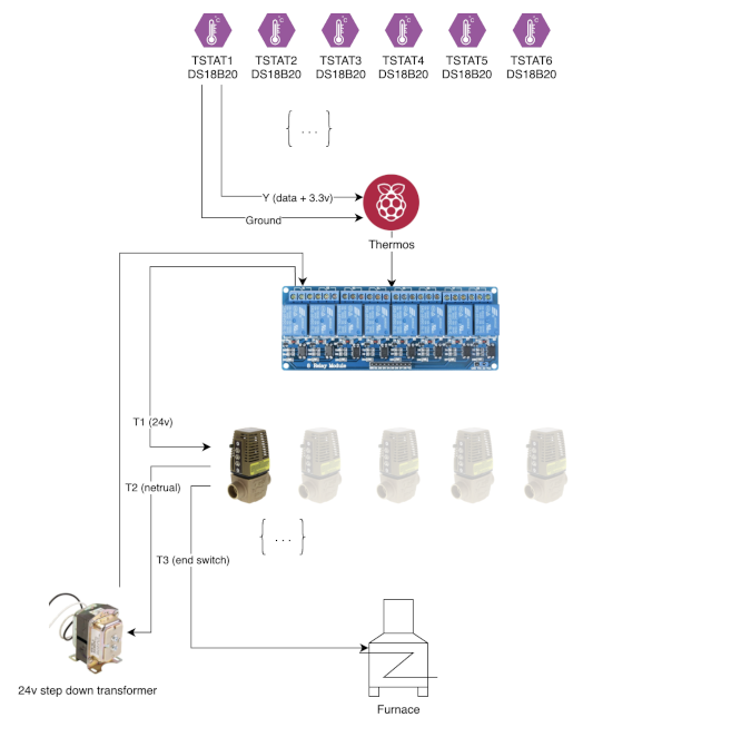
ThermOS architecture using one zone. (Joseph Truncale, CC BY-SA 4.0)
At its core, a thermostat is just a type of switch. Once the thermistor (temp sensor) inside the thermostat detects a lower temperature, the switch closes and completes the 24V circuit. Instead of having a thermostat in every room, this project keeps all of them right next to the furnace so that all six-zone valves can be controlled by a relay module using six of the eight relays. The Raspberry Pi acts as the brains of the thermostat and controls each relay independently.
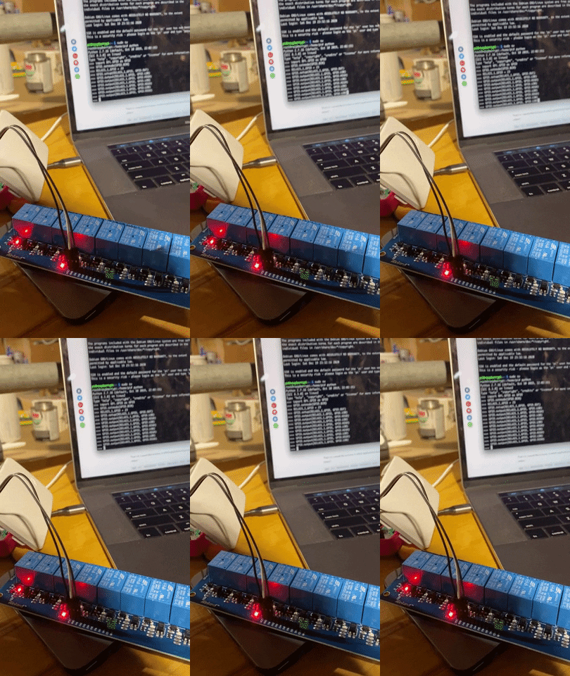
Manually setting the relays using the Raspberry Pi and Python. (Joseph Truncale, CC BY-SA 4.0)
The next problem was how to get temperature readings from each room. I could have a wireless temperature sensor in each room running on an Arduino or Raspberry Pi, but that can get expensive and complicated. Instead, I wanted to reuse the existing thermostat wire in the walls but purely for temperature sensors.
The "1-wire" DS18B20 temperature sensor appeared to fit the bill:
- It has an accuracy of +/- 0.5°C or 0.9°F.
- It uses the "1-wire" protocol for data.
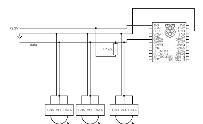
- Most importantly, the DS18B20 can use "parasitic power" mode where it needs just two wires for power and data. Just a heads up… almost all of the DS18B20s out there are counterfeit. I purchased a few (hoping they were genuine), but they wouldn't work when I tried to use parasitic power. I then bought real ones from Mouser.com, and they worked like a charm!
Three DS18B20s connected using parasitic power on the same GPIO bus. (Joseph Truncale, CC BY-SA 4.0)
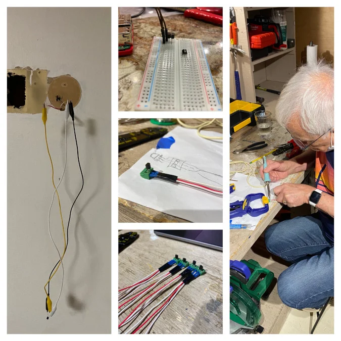
Starting with a breadboard and all the components locally, I started writing code to interact with all of it. Once I proved out the concept, I added the existing in-wall thermostat wire into the mix. I got consistent readings with that setup, so I set out to make them a bit more polished. With help from my dad, the self-proclaimed "just good enough" solderer, we soldered leads to the three-pin screw terminals (to avoid overheating the sensor) and then attached the sensor into the terminals. Now the sensors can be attached with wire nuts to the existing in-wall wiring.
The DS18B20s are attached to the old thermostat location using the existing wires. (Joseph Truncale, CC BY-SA 4.0)
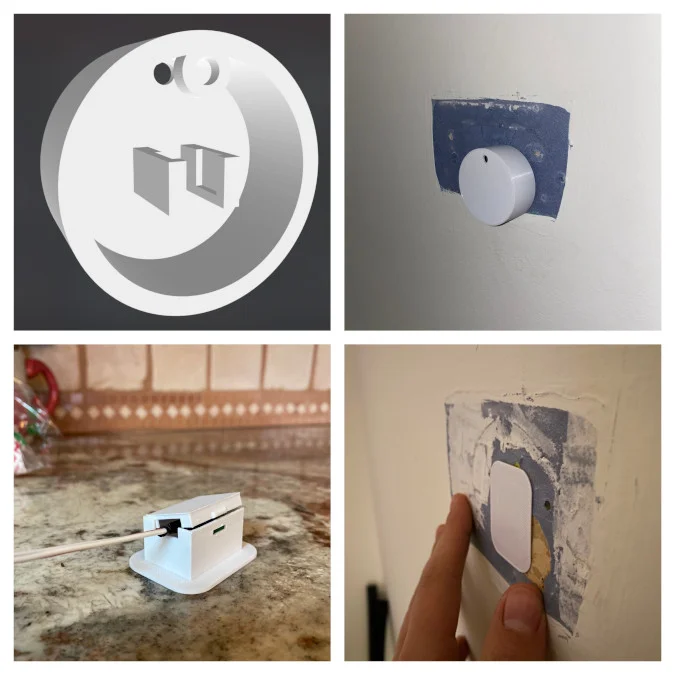
I'm still in the process of "prettifying" my temperature sensor wall mounts, but I've gone through a few 3D printing revisions, and I think I'm almost there.
I started with a Nest-style mount and made my way to a flush-mount style. (Joseph Truncale, CC BY-SA 4.0)
The ThermOS software
As usual, writing the logic wasn't the hard part. However, deciding on the application architecture and framework was a confusing, multi-day process. I started out evaluating open source projects like PiHome, but it relied on specific hardware and was written in PHP. I'm a Python fan and decided to start from scratch and write my own REST API.
Since HomeKit integration was so important, I figured I would eventually write a HomeBridge plugin to integrate it. I didn't realize that there was an entire Python HomeKit framework called HAP-Python that implements the accessory protocol. It helped me get a proof of concept running and controlled through my iPhone's Home app within 30 minutes.
Initial version of Apple HomeKit integration, with help from the HAP-Python framework. (Joseph Truncale, CC BY-SA 4.0)
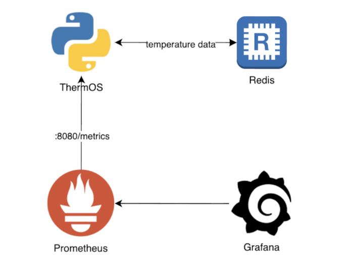
ThermOS software architecture (Joseph Truncale, CC BY-SA 4.0)
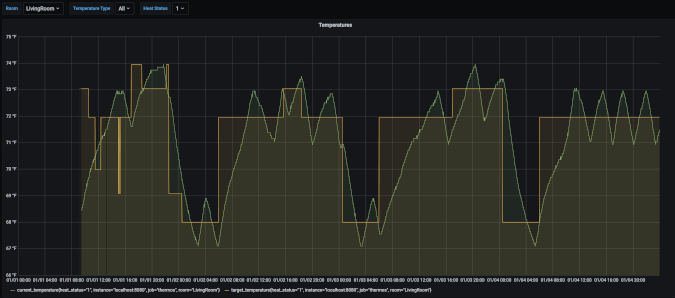
The rest of the "temp" logic is relatively straightforward, but I do want to highlight a piece that I initially missed. My code was running for a few days, and I was working on the hardware, when I noticed that my relays were turning on and off every few seconds. This "short-cycling" isn't necessarily harmful, but it certainly isn't efficient. To avoid that, I added some thresholding to make sure the heat toggles only when it's +/- 0.5C°.
Here is the threshold logic (you can see the rubber-duck debugging in the comments):
# check that we want heat
if self.target_state.value == 1:
    # if heat relay is already on, check if above threshold
    # if above, turn off .. if still below keep on
    if GPIO.input(self.relay_pin):
        if self.current_temp.value - self.target_temp.value >= 0.5:
            status = 'HEAT ON - TEMP IS ABOVE TOP THRESHOLD, TURNING OFF'
            GPIO.output(self.relay_pin, GPIO.LOW)
        else:
            status = 'HEAT ON - TEMP IS BELOW TOP THRESHOLD, KEEPING ON'
            GPIO.output(self.relay_pin, GPIO.HIGH)
    # if heat relay is not already on, check if below threshold
    elif not GPIO.input(self.relay_pin):
        if self.current_temp.value - self.target_temp.value <= -0.5:
            status = 'HEAT OFF - TEMP IS BELOW BOTTOM THRESHOLD, TURNING ON'
            GPIO.output(self.relay_pin, GPIO.HIGH)
        else:
          status = 'HEAT OFF - KEEPING OFF'
Thresholding allows longer stretches of time where the heat is off. (Joseph Truncale, CC BY-SA 4.0)
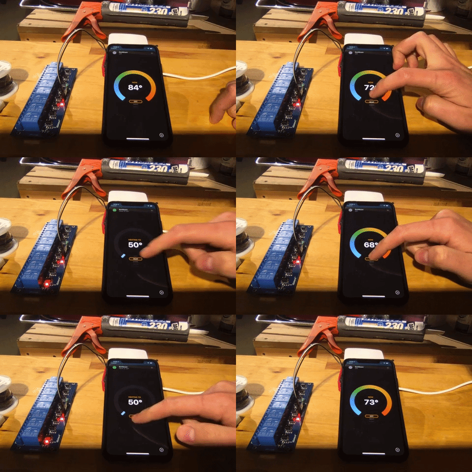
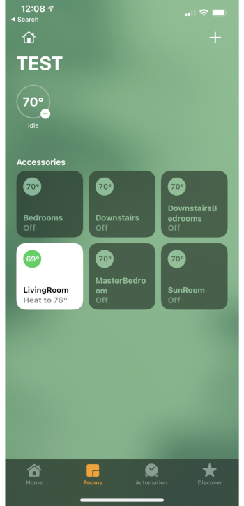
And I achieved my ultimate goal—to be able to control all of it from my phone.
ThermOS as a HomeKit Hub (Joseph Truncale, CC BY-SA 4.0)
Putting my ThermOS in a lunchbox
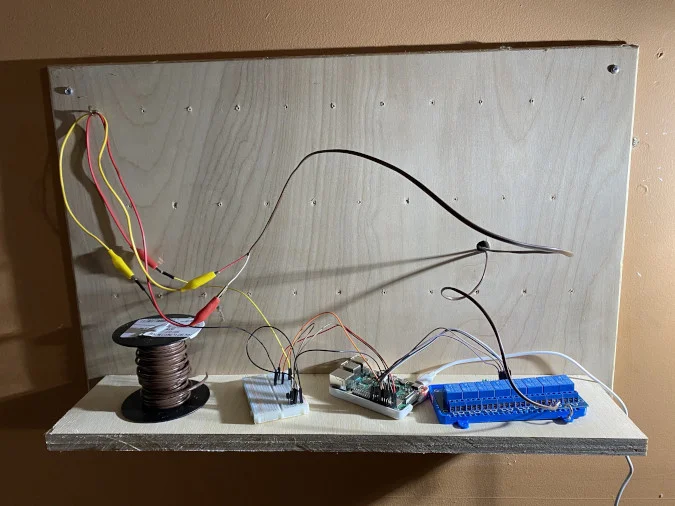
My proof of concept was pretty messy.
ThermOS controlling a single zone (before packaging it) (Joseph Truncale, CC BY-SA 4.0)
With the software and general hardware design in place, I started figuring out how to package all of the components in a more permanent and polished form. One of my main concerns for a permanent installation was to use a breadboard with DuPont jumper wires. I ordered some solderable breadboards and a screw terminal breakout board (thanks @arduima for the Raspberry Pi GPIO pins).
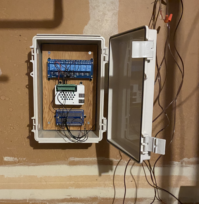
Here's what the solderable breadboard with mounts and enclosure looked like in progress.
Putting the ThermOS in a lunchbox. (Joseph Truncale, CC BY-SA 4.0)
And here it is, mounted in the boiler room.
ThermOS mounted (Joseph Truncale, CC BY-SA 4.0)
Now I just need to organize and label the wires, and then I can start swapping the remainder of the thermostats over to ThermOS. And I'll be on to my next project: ThermOS for my central air conditioning.
This originally appeared on Medium and is republished with permission.
via: https://opensource.com/article/21/3/thermostat-raspberry-pi
作者:Joe Truncale 选题:lujun9972 译者:译者ID 校对:校对者ID
