18 KiB
How to make a Raspberry Pi gamepad
This DIY retro video game controller for the Raspberry Pi is fun and not difficult to build but requires some time.
From time to time, I get nostalgic about the video games I played during my childhood in the late '80s and the '90s. Although most of my old computers and game consoles are long gone, my Raspberry Pi can fulfill my retro-gaming fix. I enjoy the simple games included in Raspbian, and the open source RetroPie project helped me turn my Raspberry Pi into an advanced retro-gaming machine.
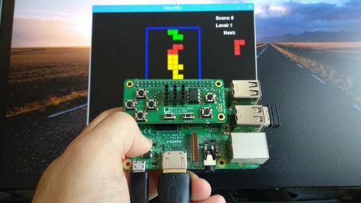
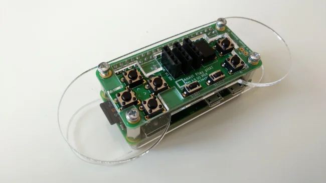
But, for a more authentic experience, like back in the "old days," I needed a gamepad. There are a lot of options on the market for USB gamepads and joysticks, but as an open source enthusiast, maker, and engineer, I prefer doing it the hard way. So, I made my own simple open source hardware gamepad, which I named the ANAVI Play pHAT. I designed it as an add-on board for Raspberry Pi using an EEPROM and a devicetree binary overlay I created for mapping the keys.
Get the gamepad buttons and EEPROM
There are a huge variety of gamepads available for purchase, and some of them are really complex. However, it's not hard to make a gamepad similar to the iconic NES controller using the design I created.
The gamepad uses eight "momentary" buttons (i.e., switches that are active only while they're pushed): four tactile (tact) switches for movement (Up, Down, Left, Right), two tact buttons for A and B, and two smaller tact buttons for Select and Start. I used through-hole tact switches: six 6x6x4.3mm switches for movement and the A and B buttons, and two 3x6x4.3mm switches for the Start and Select buttons.
While the gamepad's primary purpose is to play retro games, the add-on board is large enough to include home-automation features, such as monitoring temperature, humidity, light, or barometric pressure, that you can use when you're not playing games. I added three slots for attaching I2C sensors to the primary I2C bus on physical pins 3 and 5.
The most interesting and important part of the hardware design is the EEPROM (electrically erasable programmable read-only memory). A through-hole mounted EEPROM is easier to flash on a breadboard and solder to the gamepad. An article in the MagPi magazine recommends CAT24C32 EEPROM; if that model isn't available, try to find a model with similar technical specifications. All Raspberry Pi models and versions released after 2014 (Raspberry Pi B+ and newer) have a secondary I2C bus on physical pins 27 and 28.
Once you have this hardware, use a breadboard to check that it works.
Create the printed circuit board
The next step is to create a printed circuit board (PCB) design and have it manufactured. As an open source enthusiast, I believe that free and open source software should be used for creating open source hardware. I rely on KiCad, electronic design automation (EDA) software available under the GPLv3+ license. KiCad works on Windows, MacOS, and GNU/Linux. (I use KiCad version 5 on Ubuntu 18.04.)
KiCad allows you to create PCBs with up to 32 copper layers plus 14 fixed-purpose technical layers. It also has an integrated 3D viewer. It's actively developed, including many contributions by CERN developers, and used for industrial applications; for example, Olimex uses KiCad to design complex PCBs with multiple layers, like the one in its TERES-I DIY open source hardware laptop.
The KiCad workflow includes three major steps:
- Designing the schematics in the schematic layout editor
- Drawing the edge cuts, placing the components, and routing the tracks in the PCB layout editor
- Exporting Gerber and drill files for manufacture
If you haven't designed PCBs before, keep in mind there is a steep learning curve. Go through the examples and user's guides provided by KiCad to learn how to work with the schematic and the PCB layout editor. (If you are not in the mood to do everything from scratch, you can just clone the ANAVI Play pHAT project in my GitHub repository.)
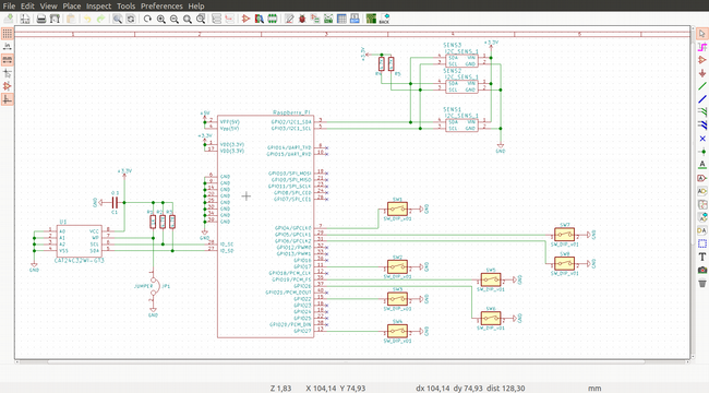
In KiCad's schematic layout editor, connect the Raspberry Pi's GPIOs to the buttons, the slots for sensors to the primary I2C, and the EEPROM to the secondary I2C. Assign an appropriate footprint to each component. Perform an electrical rule check and, if there are no errors, generate the netlist, which describes an electronic circuit's connectivity.
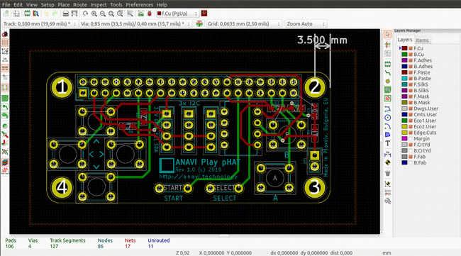
Open the PCB layout editor. It contains several layers. Read the netlist. All components and tracks must be on the front and bottom copper layers (F.Cu and B.Cu), and the board's form must be created in the Edge.Cuts layer. Any text, including button labels, must be on the silkscreen layers.
Finally, export the Gerber and drill files that you'll send to the company that will produce your PCB. The Gerber format is the de facto industry standard for PCBs. It is an open ASCII vector format for 2D binary images; simply explained, it is like a PDF for PCB manufacturing.
There are numerous companies that can make a simple two-layer board like the gamepad's. For a few prototypes, you can count on OSHPark in the US or Aisler in Europe. There are also a lot of Chinese manufacturers, such as JLCPCB, PCBWay, ALLPCB, Seeed Studio, and many more. Alternatively, if you prefer to skip the hassle of PCB manufacturing and sourcing components, you can order the ANAVI Play pHAT maker kit from Crowd Supply and solder all the through-hole components on your own.
Understanding devicetree
Devicetree is a specification for a software data structure that describes the hardware components. Its purpose is to allow the compiled Linux kernel to handle a variety of different hardware configurations within a wider architecture family. The bootloader loads the devicetree into memory and passes it to the Linux kernel.
The devicetree includes three components:
- Devicetree source (DTS)
- Devicetree blob (DTB) and overlay (DTBO)
- Devicetree compiler (DTC)
The DTC creates binaries from a textual source. Devicetree overlays allow a central DTB to be overlaid on the devicetree. Overlays include a number of fragments.
For several years, a devicetree has been required for all new ARM systems on a chip (SoCs), including Broadcom SoCs in all Raspberry Pi models and versions. With the default bootloader in Raspberry Pi's popular Raspbian distribution, DTO can be set in the configuration file ( config.txt ) on the FAT partition of a bootable microSD card using the keyword device_tree=.
Since 2014, the Raspberry Pi's pin header has been extended to 40 pins. Pins 27 and 28 are dedicated for a secondary I2C bus. This way, the DTBO can be automatically loaded from an EEPROM attached to these pins. Furthermore, additional system information can be saved in the EEPROM. This feature is among the Raspberry Pi Foundation's requirements for any Raspberry Pi HAT (hardware attached on top) add-on board. On Raspbian and other GNU/Linux distributions for Raspberry Pi, the information from the EEPROM can be seen from userspace at /proc/device-tree/hat/ after booting.
In my opinion, the devicetree is one of the most fascinating features added in the Linux ecosystem over the past decade. Creating devicetree blobs and overlays is an advanced task and requires some background knowledge. However, it's possible to create a devicetree binary overlay for the Raspberry Pi add-on board and flash it on an appropriate EEPROM. The device binary overlay defines the Linux key codes for each key of the gamepad. The result is a gamepad for Raspberry Pi with keys that work as soon as you boot Raspbian.
Creating the DTBO
There are three major steps to create a devicetree binary overlay for the gamepad:
- Creating the devicetree source with mapping for the keys based on the Linux key codes
- Compiling the devicetree binary overlay using the devicetree compiles
- Creating an .eep file and flashing it on an EEPROM using the open source tools provided by the Raspberry Pi Foundation
Linux key codes are defined in the file /usr/include/linux/input-event-codes.h. The device source file should describe which Raspberry Pi GPIO pin is connected to which hardware button and which Linux key code should be triggered when the button is pressed. In this gamepad, GPIO17 (pin 11) is connected to the tactile button for Right, GPIO4 (pin 7) to Left, GPIO22 (pin 15) to Up, GPIO27 (pin 13) to Down, GPIO5 (pin 29) to Start, GPIO6 (pin 31) to Select, GPIO19 (pin 35) to A, and GPIO26 (pin 37) to B.
Please note there is a difference between the GPIO numbers and the physical position of the pin on the header. For convenience, all pins are located on the second row of the Raspberry Pi's 40-pin header. This approach makes it easier to route the printed circuit board in KiCad.
The entire devicetree source for the gamepad is available on GitHub. As an example, the following is a short code snippet that demonstrates how GPIO17, corresponding to physical pin 11 on the Raspberry Pi, is mapped to the tact button for Right:
button@17 {
label = "right";
linux,code = <106>;
gpios = <&gpio 17 1>;
};
To compile the DTS directly on the Raspberry Pi, install the devicetree compiler on Raspbian by executing the following command in the terminal:
sudo apt-get update
sudo apt-get install device-tree-compiler
Run DTC and provide as arguments the name of the output DTBO and the path to the source file. For example:
dtc -I dts -O dtb -o anavi-play-phat.dtbo anavi-play-phat.dts
The Raspberry Pi Foundation provides a GitHub repository with the mechanical, hardware, and software specifications for HATs. It also includes three very convenient tools:
- eepmake: Creates an .eep file from a text file with settings
- eepdump: Useful for debugging, as it dumps a binary .eep file as human-readable text
- eepflash: Writes or reads an .eep binary image to/from an EEPROM
The eeprom_settings.txt file can be used as a template. The Raspberry Pi Foundation and MagPi magazine have helpful articles and tutorials, so I won't go into too many details. As I wrote above, the recommended EEPROM is CAT24C32, but it can be replaced with any other EEPROM with the same technical specifications. Using an EEPROM with an eight-pin, through-hole, dual in-line (DIP) package is easier for hobbyists to flash because it can be done with a breadboard. The following example command creates a file ready to be flashed on the EEPROM using the eepmake tool from the Raspberry Pi GitHub repository:
./eepmake settings.txt settings.eep anavi-play-phat.dtbo
Before proceeding with flashing, ensure that the EEPROM is connected properly to the primary I2C bus (pins 3 and 5) on the Raspberry Pi. (You can consult the MagPi magazine article linked above for a discussion on wiring schematics.) Then run the following command and follow the onscreen instructions to flash the .eep file on the EEPROM:
sudo ./eepflash.sh -w -f=settings.eep -t=24c32
Before soldering the EEPROM to the printed circuit board, move it to the secondary I2C bus on the breadboard and test it to ensure it works as expected. If you detect any issues while testing the EEPROM on the breadboard, correct the settings files, move it back to the primary I2C bus, and flash it again.
Testing the gamepad
Now comes the fun part! It is time to test the add-on board using Raspbian, which you can download from RaspberryPi.org. After booting, open a terminal and enter the following commands:
cat /proc/device-tree/hat/product
cat /proc/device-tree/hat/vendor
The output should be similar to this:
If it is, congratulations! The data from the EEPROM has been read successfully.
The next step is to verify that the keys on the Play pHAT are set properly and working. In a terminal or a text editor, press each of the eight buttons and verify they are acting as configured.
Finally, it is time to play games! By default, Raspbian's desktop includes Python Games. Launch them from the application menu. Make an audio output selection and pick a game from the list. My favorite is Wormy, a Snake-like game. As a former Symbian mobile application developer, I find playing Wormy brings back memories of the glorious days of Nokia.
Retro gaming with RetroPie
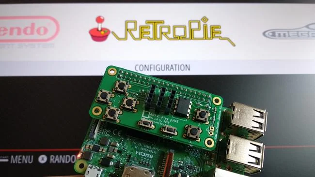
Raspbian is amazing, but RetroPie offers so much more for retro games fans. It is a GNU/Linux distribution optimized for playing retro games and combines the open source projects RetroArch and Emulation Station. It's available for Raspberry Pi, the Odroid C1/C2, and personal computers running Debian or Ubuntu. It provides emulators for loading ROMs—the digital versions of game cartridges. Keep in mind that no ROMs are included in RetroPie due to copyright issues. You will have to find appropriate ROMs and copy them to the Raspberry Pi after booting RetroPie.
The open source hardware gamepad works fine in RetroPie's menus, but I discovered that the keys fail after launching some games and emulators. After debugging, I found a solution to ensuring they work in the game emulators: add a Python script for additional software emulation of the keys. The script is available on GitHub. Here's how to get it and install Python on RetroPie:
sudo apt-get update
sudo apt-get install -y python-pip
sudo pip install evdev
cd ~
git clone <https://github.com/AnaviTechnology/anavi-examples.git>
Finally, add the following line to /etc/rc.local so it will be executed automatically when RetroPie boots:
sudo python /home/pi/anavi-examples/anavi-play-phat/anavi-play-gamepad.py &
That's it! After following these steps, you can create an entirely open source hardware gamepad as an add-on board for any Raspberry Pi model with a 40-pin header and use it with Raspbian and RetroPie!
What's next?
Combining free and open source software with open source hardware is fun and not difficult, but it requires a significant amount of time. After creating the open source hardware gamepad in my spare time, I ran a modest crowdfunding campaign at Crowd Supply for low-volume manufacturing in my hometown in Plovdiv, Bulgaria. The Open Source Hardware Association certified the ANAVI Play pHAT as an open source hardware project under BG000007. Even the acrylic enclosures that protect the board from dust are open source hardware created with the free and open source software OpenSCAD.
If you enjoyed reading this article, I encourage you to try creating your own open source hardware add-on board for Raspberry Pi with KiCad. If you don't have enough spare time, you can order an ANAVI Play pHAT maker kit, grab your soldering iron, and assemble the through-hole components. If you're not comfortable with the soldering iron, you can just order a fully assembled version.
Happy retro gaming everybody! Next time someone irritably asks what you can learn from playing vintage computer games, tell them about Raspberry Pi, open source hardware, Linux, and devicetree.
via: https://opensource.com/article/19/3/gamepad-raspberry-pi
作者:Leon Anavi 选题:lujun9972 译者:译者ID 校对:校对者ID
